|
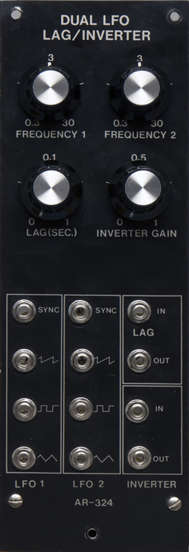
Aries AR-324 |
|
Aries modules were available both as kits and factory modules. This module sold in 1977 for $71.00 in kit form or $127.00 assembled. This module appear to be a kit due to the non-uniformity of components, component errors, and build and solder quality.
I combined specifications and schematics from Robert Leiner (with permission) and my photos into a PDF document.
AR-324 Dual LFO-Lag-Inverter Document
Aries AR-324 Documentation (compliments of Michael Gilbert)
I have not been able to find PCB layout information. Some components are placed somewhat randomly on the PCB so tracing the circuit takes time. Access to portions of the PCB component side is also challenging due to the bundle of front panel wires.
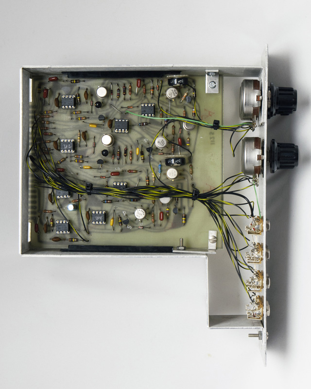
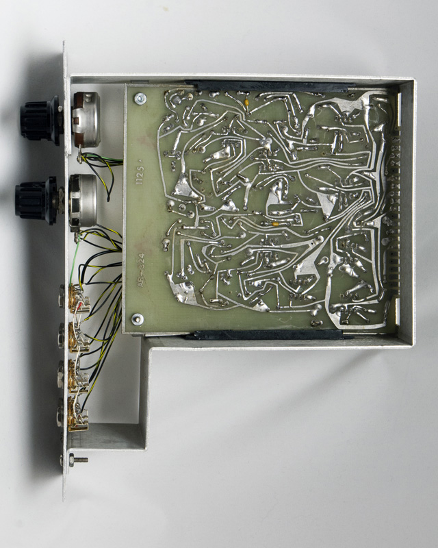
The PCB is a single sided tin with no solder mask. I did find a short between runs that looked suspiciously like a tin whisker! Care is required when doing repairs as the pads do lift easily.
The AR-324 LFO has a core for the triangle and square wave and a separate core for the sawtooth wave. A dual NPN transistor controls the current to both cores and a trimmer adjusts the sawtooth amplitude. The sawtooth core is reset by the square wave output through C8. I found that the reset pulse was too short to fully discharge C3 to the negative rail so the sawtooth waveform drifts up to the +15V power supply. Increasing C8 to 0.1 µF resets the waveform nicely although the amplitude decreases slightly at higher frequencies. I have found and corrected one error on the schematic so am not sure that I trust the printed capacitor value. The top PCB rail interfered with the sawtooth trimmer which is another indication that this was most likely built as a kit.
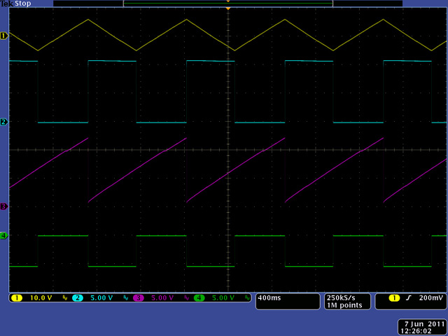
This scope image shows the three outputs from the LFO and also the square wave inverted at 50% amplitude. Note that the triangle output is +/- 5 volts while both the square and sawtooth outputs are 0 to 10 volts.
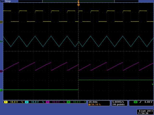
This scope image shows the three outputs from the LFO reset with the rising edge of a sync signal.
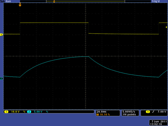
This scope image shows the operation of the lag circuit with a square wave input.