 |
Ian Fritz 'Threeler' |
|
I built an Ian Fritz Threeler VCF module from Bridechamber as discussed on the Electro-Music and on the Muffwiggler forums. I like the various modes that this filter offers and it has really crazy performance.
Modifications
Bridechamber provides the Threeler documentation which has the parts list modified for +/-15 volt operation. The schematics however still show the component values for +/-12 volts. This table lists the resistor value changes for the different supply voltages.
| Reference Designator | +/-12 V value |
+/-15 V value |
| R6, R13, R19, R24 | 68K | 82K |
| R28, R43 | 120K | 150K |
| R35 | 270K | 330K |
| R41 | 330K | 390K |
I found that my filter had a "dead zone" where the outputs would drift to negative DC voltages at the very low end of the frequency range . I think this is due to variations in OTA performance. I've always found that OTAs from different batches always require a bit of tweaking to the circuit. I added some DC bias to the A6a CV summation node to eliminate the "dead zone" and discovered that the offset required was equal to the bias supplied by R35. I simply removed R35 from the circuit.
I also discovered that Out3 required some amount of Resonance to be operational. I added a 1M5 resistor from +15 volts to the A7a CV summation node so that Out3 was always operational.
|
Assembly Notes:
Modifications:
Notes:
|
Waveforms
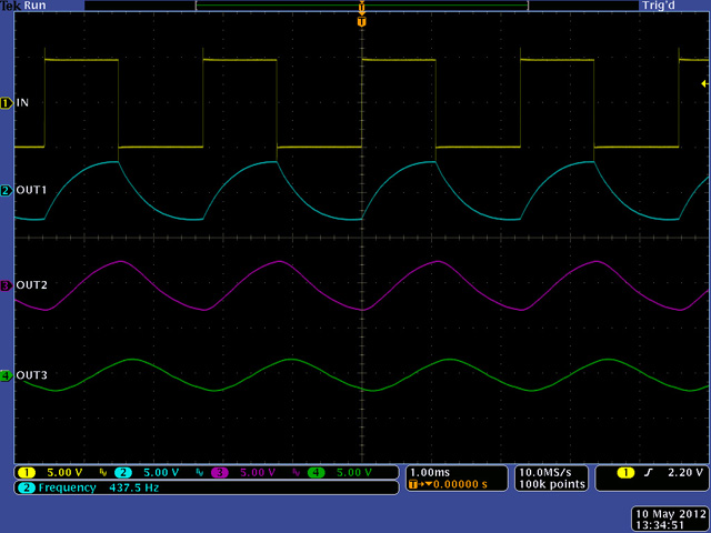
This filter has some great performance in each of the four modes. This scope image shows the filter on a 440Hz square wave input in Low-Low-Low mode.
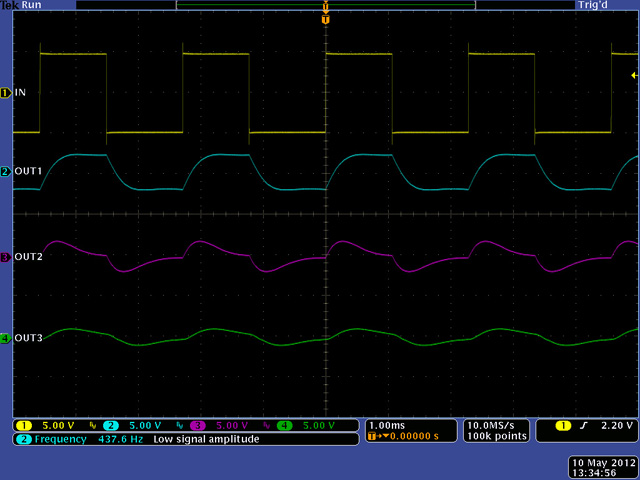
This scope image shows the outputs with the same input and settings in Low-High-Low mode.
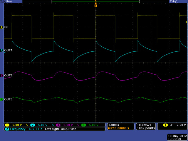
This scope image shows the outputs with the same input and settings in High-Low-High mode.
This scope image shows the outputs with the same input and settings in High-High-High mode.

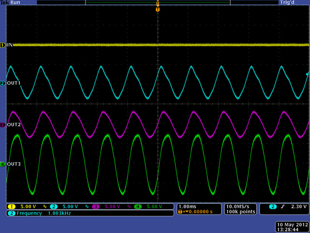
This scope image shows the self-resonance at 1KHz in Low-Low-Low mode.
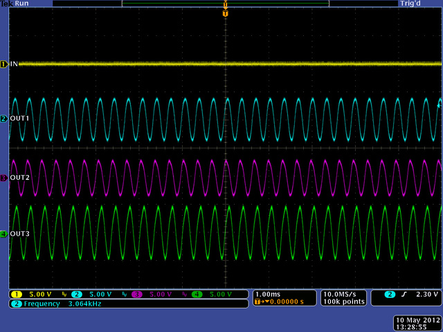
Switching to Low-High-Low mode increases the self-oscillation frequency to 3 KHz.
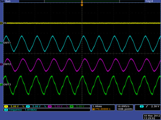
Switching to High-Low-High mode drops the frequency back to 1 KHz with a slightly more triangular waveshape.
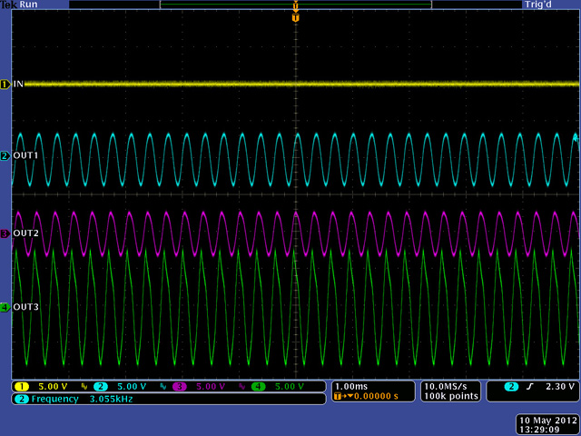
Switching to High-High-High mode increases the frequency back to 3 KHz with a larger Out3 level.
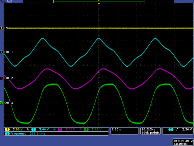
The lowest frequency in self-oscillation mode is 0.3 Hz.
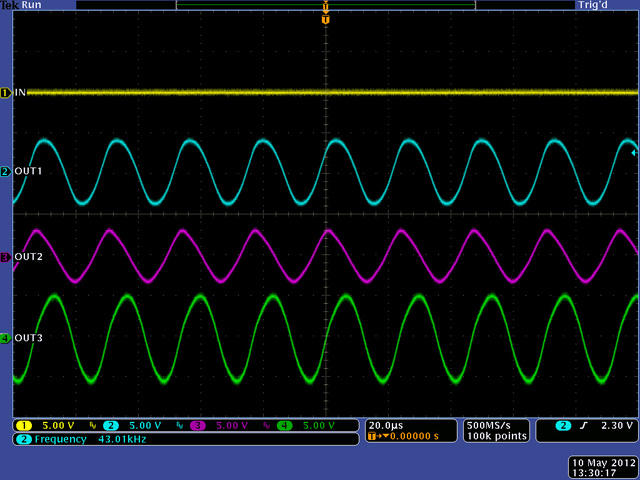
The highest frequency in self-oscillation mode is 43 KHz.
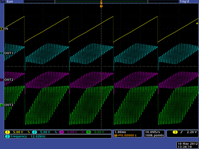
This scope image shows a 440 Hz ramp waveform with high resonance in Low-Low-Low. Wild.
Construction
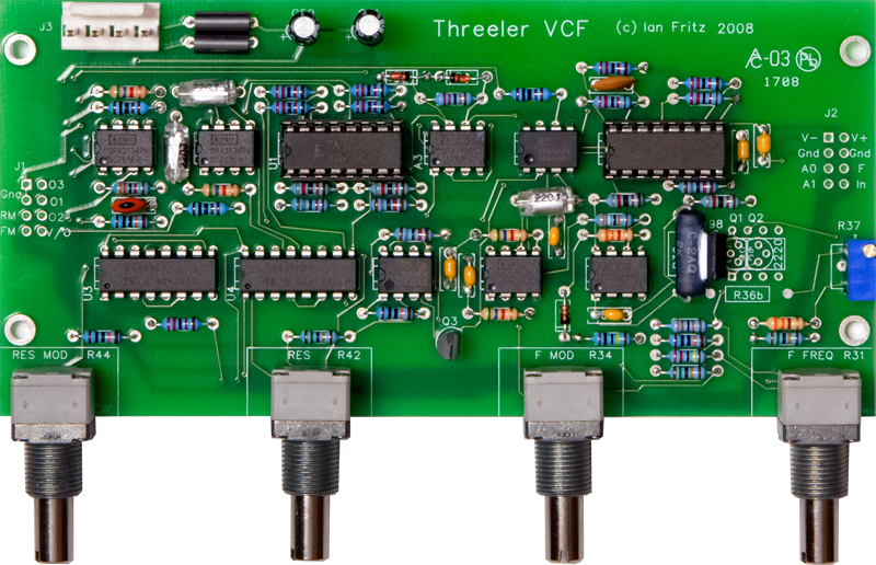
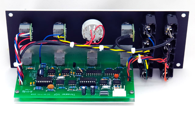
I made my own bracket for mounting the PCB out of 0.050" aluminum. You can see the addition of the second FM control and the 1M5 resistor on top of A7 in this photo.
Panel
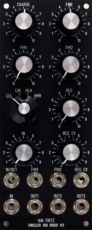
I designed my own MOTM-style 2U panel and added a second FM jack and control since there was panel space and it is is a simple addition to the circuit. I used legends that were more uniform with my other modules and would indicate the corresponding output for the various modes.
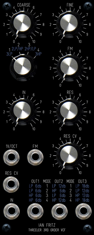
The panel on the right is a concept design that uses light blue legends to indicate the filter output for each of the 4 modes.
DJB Threeler FrontPanelExpress file