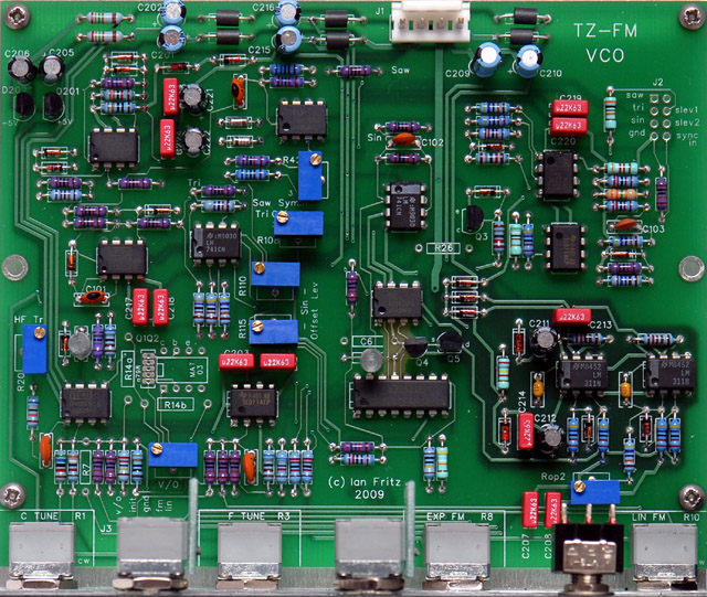
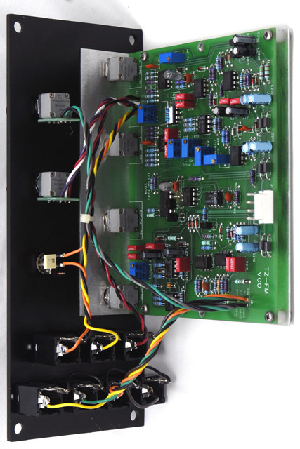
I built the Thru-Zero
VCO as discussed on the Electro-Music
forum. I've modified the design so it operates on +/- 15 volts
supplies. I've yet to install Q102, R14, R26 and C6 in this
image and the panel mounted controls and switch show across the bottom. The PCB assembly is pretty straightforward but there are a couple of
items worth noting.
|
Assembly Notes:
-
J1
is rotated 180 degrees from most MOTM-compatible PCBs! The polarizing flat portion of the connector is
oriented towards the edge of the PCB.
-
C1
is not located on the PCB. It solders directly to the Lin FM
AC/DC switch.
-
J2
slev1 connects to the Sync potentiometer CCW pin (marked '1' on
Spectrol/Vishay potentiometers). J2 slev2 connects to
the Sync potentiometer wiper (marked '2'). The Sync potentiometer
CW pin (marked '3') connects to ground (I connected to the
unused hole on J2 and jumpered the pad to ground on the rear of the PCB).
-
The
tempco mounts in R14a if Q102 is an inline part (2SA798) or R14b if Q102 is a
DIP part (MAT03/ SSM2220).
-
Step one of the waveform adjustment to
the "Saw symm" trimmer should read R42,
not R43.
-
I found that I could improve
the symmetry at the top of the triangle by changing C6 to 33 pF. It
took some tweaking between the "Saw symm" and the
"Thresh trim" adjustments to make the triangle peaks match
for both the integrator upramp and downramp.
|
I purchased the parts kit from Bridechamber.
Here are some notes on the components included in the kit.
|
Bridechamber Parts Notes:
-
C1
is a yellow box capacitor marked '.1'.
-
C3
is a silver axial polystyrene capacitor marked '221J'. The leads need
to be bent to fit the radial PCB pattern.
-
C4
is a silver radial polystyrene capacitor marked '1000J' The
leads need to be bent to fit the axial PCB pattern.
-
C6,
C7, and C8 are small yellow axial ceramic capacitors marked '220'.
-
C9
and C101 are radial disc ceramic capacitors marked '10'.
-
C102
is a radial disc capacitor marked '47'
-
C103
is a radial disc capacitor marked '331'.
-
All
0.22 uF capacitors are red box and marked 'µ22K63'.
-
D12
and D13 (matched 4.3V zener diodes) had their leads bent in a circle.
-
All
other zener diodes were marked with the voltage rating on masking tape
around the bodies.
-
There
are six zener diodes not listed in the BOM that replace the six ferrite beads
for the +/-15 volt modification described in the addendum.
-
D201
and D202 are TO-92 packages similar to the transistors.
-
The
2K tempco resistor had its leads bent in a circle.
-
Some
of the resistors were a purple body which made it difficult to
accurately identify some of the color bands. I used an ohm meter
to verify each resistor value.
|
Here are my design changes for operating this VCO on 15 volt
supplies. There were just a few parts to change - four zener diodes and
six resistors.
|
15 volt power supply
modifications:
I
never built the TZ-FM module with the original values for 12 volt
operation so I can't verify that each change is absolutely required for
15 volt operation. These are the changes I made and verified for my module.
I used 1% resistor standard
values. I would think that the closest value 5%
tolerance resistors would work fine.
TZ-FM
Schematics part 1
-
Change
R28 from 18K to 27K4 to keep the gate off voltage at -6.3
volts.
TZ-FM
Schematics part 2
-
Change
R116 from 390K to 487K to keep Iabc at 58.4 µA.
-
Change
R119 from 22K to 30K to keep a 0 to 3.75 volt range at the negative
input of A9a. (I used a 100K potentiometer for R120 so changed R119 to
300K). Note that Ian later changed this resistor to 12K so the
change for 15V would be to use 18K. (* See note below)
-
Change
R128 from 47K to 59K to keep the negative input of A10 at 0.65
volts. Probably not required as it keeps the sync
reference level at 0.65 volts instead of increasing to 0.81 volts
-
I
did not change any other values in the sync circuit. A9 and A10
both operate as comparators with rail to rail output. While
the output is higher with 15 volt supplies, the ratio between the
R123-R124-R130-R131 and R132-R133 dividers remains constant.
Note that Ian mentions R132 and R133 are reversed in the build
documents. R132 should be 22K and R133 should be 27K.*
TZ-FM
Schematics part 3
-
Change
R201 and R202 from 1K8 to 2K55 to keep the current at 3.88 mA. Probably
not required
-
Change
D203 and D204 from 5.1V to 8.2V (1N5237B) to keep the U2 and U3 supply at +/-7
volts.
-
Change
D205 and D206 from 3.3V to 6.2V (1N5234B) to keep the A4 supply at +/- 9 volts (on Part 1 this supply is mislabeled as
+/-8V)
Notes
-
+15
volts measured ~90 mA; -15 volts measured ~80 mA.
* Muffwiggler topic Teezer
15V build question details these changes. R119 was later changed to
12K for a softer sync. |
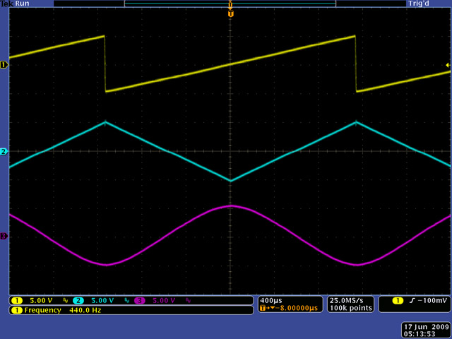
Waveforms
Here are all three outputs at 440 Hz. I
was able to improve the triangle symmetry on my module by increasing the value
of C6. I experimented with different values and was able to minimize the glitch
that is visible at the top of the triangle
wave. Careful adjustment of the trimmers is required.
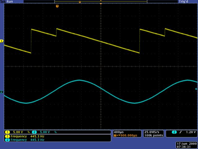
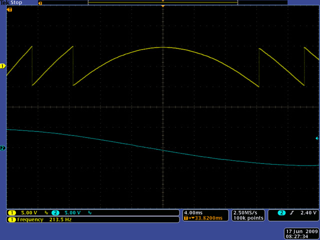
This image shows the VCO sync'd to a sine wave of a slightly
slower frequency.
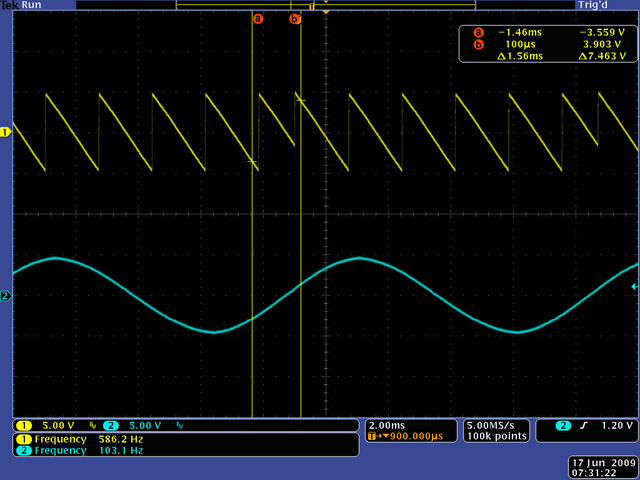
This image shows the VCO sync'd to a sine wave of a much lower
frequency. You can see the truncated saw between the vertical cursors.
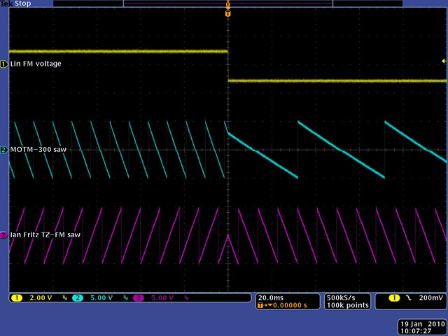
The way I think of the operation of a thru-zero oscillator is
that the absolute value of the linear FM voltage changes the frequency and
the sign of the linear FM voltage determines the polarity. In this scope image I
compare the output of a MOTM-300 VCO to the Ian Fritz TZ-FM VCO. Both
oscillators are set to the same frequency with the same positive linear FM
voltage (note the slope is different between these two
oscillators). As the linear FM voltage steps negative, the MOTM-300
reduces in frequency while the TZ-FM stays at the same frequency but the slope changes polarity.
Here is another scope image of thru-zero operation with a slow
changing linear FM voltage. The output slope gracefully changes polarity.
Construction
I used the Bridechamber panel for my module.
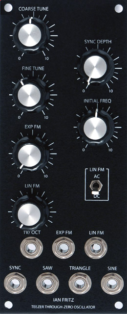
I made a bracket to mount the PCB out of 0.050" aluminum.
I used P260P
potentiometers from BI
Technologies, and potentiometer chiclets
from John Loffink.
back
