|
Thomas Henry Mega
Percussive |
|
I wanted some type of percussion module and was looking at the Barton Musical Circuits BMC023 Decaying Analog Noise and the BMC025 FM Drum but decided to go with the full featured Thomas Henry Mega Percussive Synthesizer (MPS) as described on the Scott Stites Birth Of A Synth site and there is an Electro-Music The Thomas Henry Mega Percussive Synthesizer forum as well as a Mega Percussive Synth Muffwiggler forum for the module.
The PCB can **possibly** be purchased at Electro-Music. I found out the hard way that the Electro-Music store gives no order acknowledgement such as an email or an order number. Multiple messages via the "Contact Us" link go unanswered as do emails to the Admin or the moderator. I did find the topic Thomas Henry MPS Boards Are On Sale which details similar experiences from others ordering from Electro-Music. We'll see if I ever get a PCB or if I just chock this up as a bad purchase.
Happily Synthcube sent me a PCB so I could complete this module. A big thanks to them!
I wanted to use MTA connectors for the x8 connectors to ease panel wiring using x1, 2, 3, and 4 pin connectors but they don't make a 1 pin. I've used FCI crimp connectors so found a 1 pin 649-65039-036LF plastic housing but it costs $1.32! Together with the 649-48235-000LF pin it costs $1.67 per connection! The FCI 649-HT-95 crimp tool is only a mere $1,227.56 - sheesh. I found this Pololu crimp tool at a more reasonable $34.95 and they have various size housings in quantities of 25 for less than $1.00 per pack. Their female and male square pins are affordable and seem to be tin versions of the FCI pins. I used gold pin headers and FCI pins with Pololu headers.
Here is my wiring connector organization: (some errors on the original diagram have been corrected)

MPS Panel Wiring (PDF file) Updated
|
Modifications: I only made just a few modifications. Potentiometer values
Manual Trigger
Operation
Notes
|
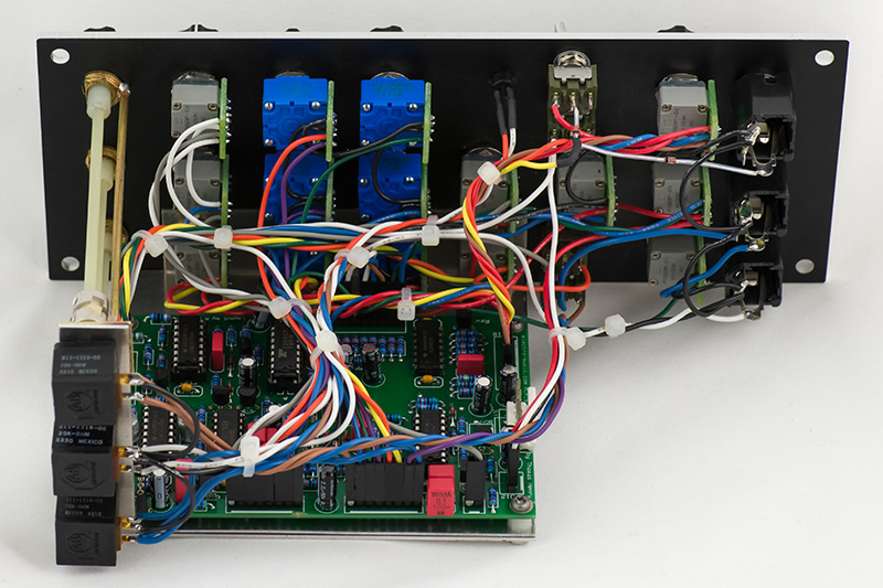
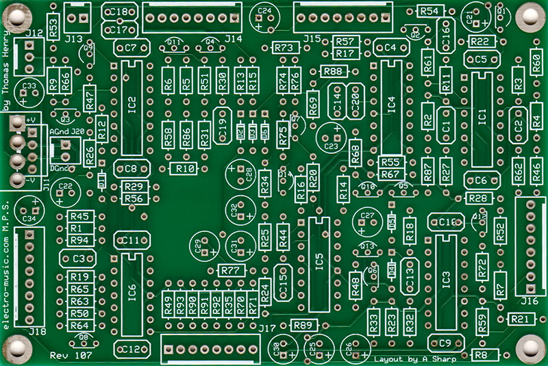
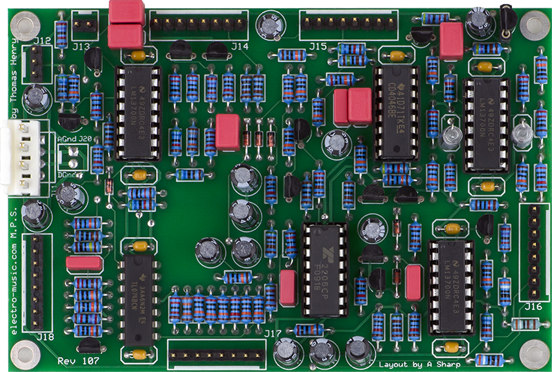
Construction
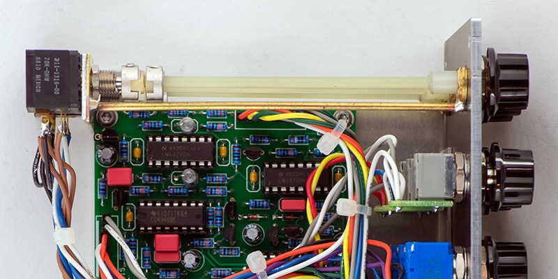
I used gold square pin strips that I had in stock for the connectors. The 0.1 uF box mylar capacitors are a bit large for C17, C18, and C20 and need to have their leads bent just a bit to fit. I used a socket for Q1 so I could try different transistors for the noise source.
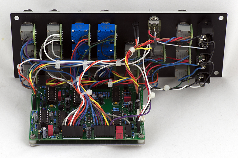
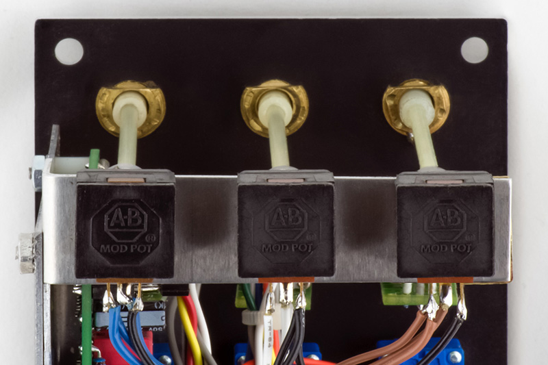
I made my PCB bracket out of 0.050" aluminum and mounted it with four potentiometers. I made a separate page on making PCB brackets and have more photos of the MPS bracket there. I used BT Technologies P260P potentiometers for the 100K controls and changed the Sensitivity and the three Mixer controls to 100K. I used Bourns 91 series for the 10K Sweep and 1M Decay controls.
The wiring was just a bear as there is no organization to the layout. It just leads to a rat's nest of wiring. A bit more time during the PCB layout would have improved this PCB considerably. I 'or'ed the trigger jack and trigger switch with two diodes that can be seen in the photo.
Operation
The operation and controls are reasonably well defined on the Scott Stites Birth Of A Synth site with the exception of the ring mod balance control. It simply says "... the ring mod balance control ... lets you balance or deliberately unbalance the ring modulator for an immense range of weird clangorous sounds."
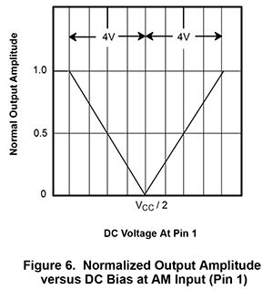
Pin 1 of the XR-2206 is the AM modulation input for the four quadrant multiplier. If this voltage is set at Vcc/2 then the output of the four quadrant multiplier is off. The four quadrant multiplier has maximum gain towards either supply rail which correspond to the CW and CCW position of the RM Balance control. Thus when not using the ring modulation function you need to turn the RM Balance to one of the extremes (the difference is the phase although on mine CW is louder than CCW). When using the ring modulation function you can then turn the RM Balance to whatever you choose but centered will minimize the signal bleed through. The operation of the AM Modulation Input is shown below from the Exar XR-2206 datasheet (I believe the 14 volts in the description below should be 4 volts).

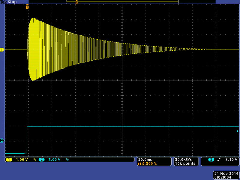
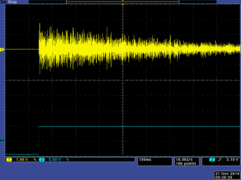
I have just a few scope photos for this module. This first is the Impact envelope with Sweep set to 50% and Decay set to 75%.
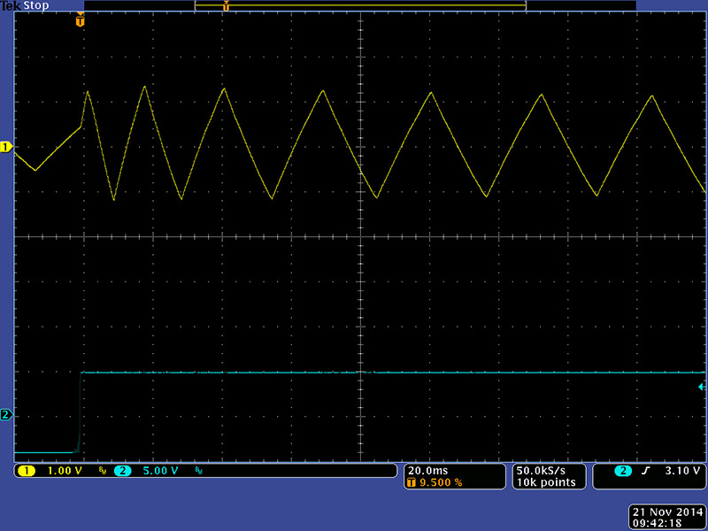
This is the shell output with a long decay and no ring modulation.
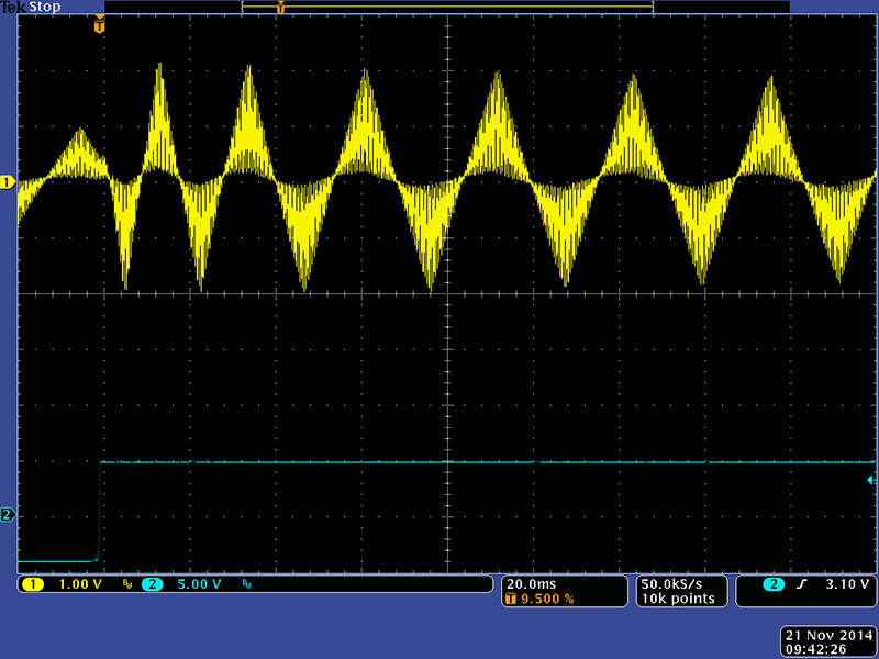
This is the same setup but with ring modulation depth set to maximum.
This is the noise envelope with decay set to maximum.
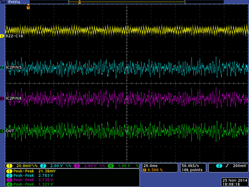
When listening to the module there was clearly something wrong with the Impact section. The Impact decay was a bit erratic where sometimes the decay would be longer. On the scope I could see a re-trigger of the Impact envelope. I traced it back to glitches on the output of the trigger comparator IC2 (green trace).
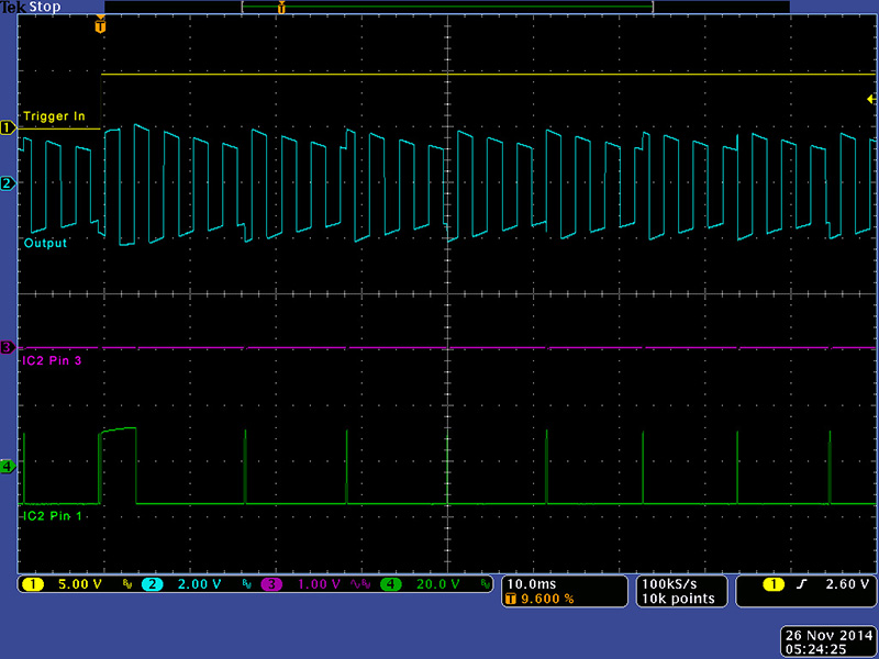
Putting my scope probe on IC2 pin 3 (the high impedance input) made it behave quite well so I simply added a 51 pF capacitor across R94.

Output Levels
There has been some discussion on the forums about low output levels. Rather than calculate the levels I chose to simply measure mine. The Locked feature makes it easy to measure the various levels. I measured the levels through the circuit at the source, at the VCA, and at the output. The output mixer attenuates all the signals by 2 to keep the output when all the signals are mixed to just less than 10V pk-pk. Here the Impact output level is 4.3V pk-pk.
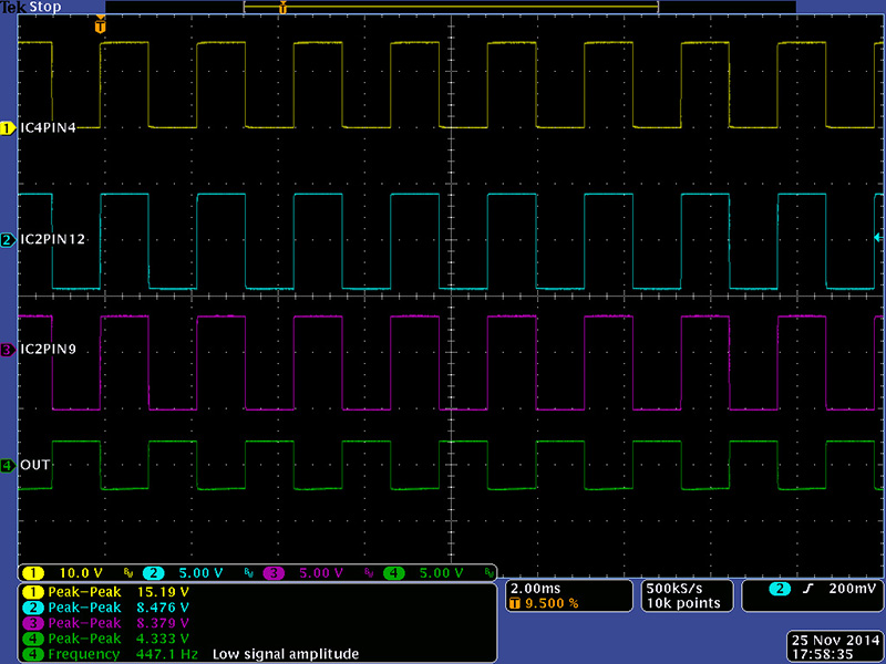
R44 sets the XR-2206 output level to 2.2V pk-pk and the shell output level is lower at 2.7V pk-pk.
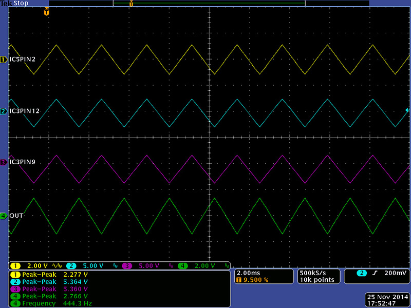
The noise output level is also low at 1.3V pk-pk.
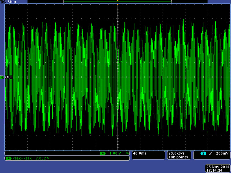
When all three outputs are mixed full the output level is 8V pk-pk. This module could be run a little hotter by decreasing the mixing resistors R90, R91 and R92.
I thought the Shell and Noise levels were too low so I adjusted the resistors to better balance the gains.
| Section | Resistor | Gain | Gain Change |
| Impact | R92=200K | -0.5 | No Change |
| Shell | R90=49K9 | -2 | 4X |
| Noise | R91=100K | -1 | 2X |
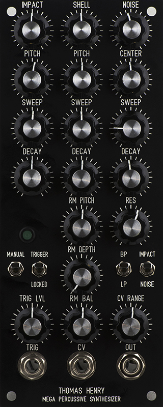
Panel
I did a 3U layout but the panel was pretty sparse. I was influenced by sduck's design for a 2U panel and went for tight vertical spacing of the potentiometers. I put the mixer controls across the top so the controls label the columns for Impact, Shell, and Noise. The only variant on this is the CV Range control which is to the right of the Shell column but is associated with the CV jack. I also thought a manual trigger switch would be useful for adjusting all of the controls. Note this design has only 3/8" clearance above the top potentiometers so requires notching the top mounting rail.
DJB-Thomas Henry MPS FrontPanelExpress HPGL design file This design has only 3/8" clearance above the top potentiometers!
I decided after it was built that I really didn't want to notch the top mounting rail. I wanted to mount this in my wood cabinet and behind the mounting rail is a wood strip. I decided instead to move the top controls to the rear and use extensions to the front panel knobs to provide clearance over the rail and wood strip.
I made 1/4" bushings from surplus potentiometers and milled the top flange off so I would have a full 1/2" of clearance. I made a potentiometer bracket that would mount to the bracket by two rear PCB holes. I shorten those standoffs by the thickness of the additional bracket.
I made a brass rod and soldered it to the bushing to provide structure to the far side of the potentiometer bracket. The shafts are made of 1/8" fiberglass glued into 1/4" nylon standoffs to mount the knobs. I used flex couplers to accommodate any misalignment between the knob and potentiometer.
The modification came out very well and fits nicely in my wood cabinet.