 |
Electronic Projects |
|
Elks 11th Hour Clock Redesign

FM Transmitter
I bought the Niigata NS73M FM transmitter module from Sparkfun. I prototyped it with my AVR Butterfly module using the Nuts & Volts May 2008 article. I reduced the code size by taking out the audio generator so it would compile with the Bascom-AVR demo software.
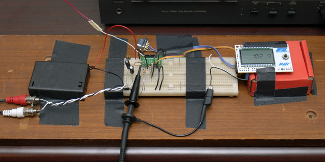
I wrote a Basic program for an ATTINY13 to initialize the NS73M at a fixed frequency of 102.9 MHz. The Bascom-AVR compiler I2C support made the program quite easy. 9 bytes of data is all that is required to program the NS73M.
![]()
The finished FM transmitter is very simple consisting of a 3V regulator, ATTINY13, NS73M, and a handful of passive components. I get good coverage through the entire house with a 32" antenna.
![]()
DJB-FM transmitter Basic source code
Pi Musicbox
I have a NAS with all my music on it and wanted some dedicated hardware (i.e. not a windows computer) to access it. I experimented with the XBMC build on the original Raspberry Pi but decided it was overly complicated and a but clumsy and slow. Later when the Raspberry Pi 2 B came out I decided to try the Pi Musicbox. I got this to work reasonably well but the journey took a lot of trial and error. I imaged V6 onto an SD card but my first roadblock was I still have WEP wireless. The Settings.ini file is only setup for WPA so I had to edit the /etc/network/interfaces file. The first issue was logging into the OS. The various pages I found neglected to tell me the username (root) and the password (musicbox). Simple enough. I found this site and modified the instructions for WEP with a static IP.
auto lo
iface lo inet loopback
iface eth0 inet dhcp
allow-hotplug wlan0
auto wlan0
iface wlan0 inet static
wireless-essid yournetwork
wireless-key yourkey
address yourstaticip
subnet yoursubnet
gateway yourgateway
That got me up and running with WEP. I was then able to connect with a browser but none of the buttons did anything. I spun on this for a long time until I figured out Musicbox doesn't work with IE below V10. I simply changed to Chrome and it worked so I could complete some additional configurations. I was unable to connect to my NAS until I added .local after the NAS name. Then it scanned my NAS for a very long time (18,000+ songs). When complete I was unable to reconnect with Chrome. I suspected that I might have run out of memory so I rebuilt the system and this time checked the Resize Filesystem to On before setting the path to my NAS. This time after scanning I could connect with Chrome. I don't know how to correlate the size of the SD card to the number of songs but I used an 8GB card. In the end I did not configure anything in the Settings.ini file.
The system works reasonably well. I did get a lot of buzz in the audio when I had a HDMI monitor connected. My album cover art is in each folder as a .jpg and a .png but none show up. I suspect the album art has to be embedded in the mp3 and flac files to be visible. I wish the browser interface was a bit more sophisticated with bookmarks for web streaming. Supposedly you can bookmark these in the browser but I have been unable to have any retained. I have the musicbox interfaced to my Dynaco stereo system and it works very nicely.
I decided to install Pi Musicbox on my original Raspberry Pi B and it works but is a bit slower in responsiveness. I decided to install it in my shop so I could listen to my music. It is a bit far from my wireless access point so I didn't get reliable reception. The solution was to move it to the front corner of my shop and then use my FM transmitter to broadcast the audio to my stereo in the back of the shop.
Scrolling Car Display
This project is a follow-on from PSIM display work. Since this VFD easily interfaces with 9600 baud serial I decided to build a scrolling message board. I chose the ATTINY13 processor because of it's small size. I ported the Atmel AVR304 application note implementing a software uart to the ATTINY13 processor and used an additional pin to blank the display.
Vacuum fluorescent display software source code
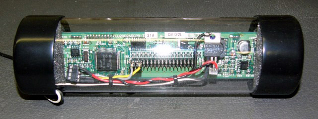
I set the display to 50% brightness which limits the total power consumption to ~280 mA. I used a LM2940 low dropout regulator to be able to power this from a 6 volt battery in my 1949 Chevy. I assembled the display in a 1.5" clear plastic tube. The ATTINY13 is the small DIP on the left at the end of the wires and the LM2940 regulator is on the right mounted to the 2 pin power connector.
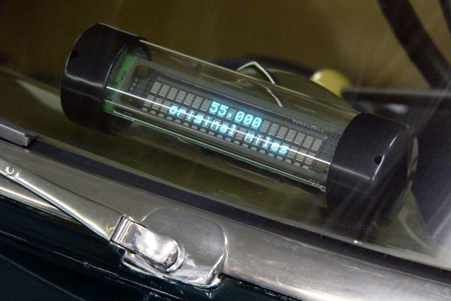
Here is the display on the dashboard of my 1949 Chevy. It slowly scrolls information on the car including the name, year, model number, mileage, original content, and owner.
6V Car Battery Float Charger
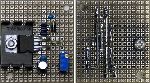
I two 1949 Chevrolet cars with 6 volt car batteries. I don't drive them during the winter so I am constantly having to keep the batteries charged. Most automotive chargers are 12 volts and if they have a 6 volt setting they are manual charge only. I wanted a continuous unit that would not overcharge the battery. A lead acid battery can be maintained at full charge without overcharging with a constant voltage of 2.25 ~ 2.30 volts per cell so I designed a float charger using a 9VDC wall wart with a post regulator set to 6.75 volts and a 100 mA current limit.
Reel Tape Box Display
I have a variety of reel tapes and some of the boxes have interesting covers. I made a frame with a glass front with inside dimensions tight enough that the tape boxes simply press in from the rear.
