Jürgen Haible
Living VCO

Note:  The original Jürgen Haible website is no longer active but PCBs are being released at http://www.jhaible.com.

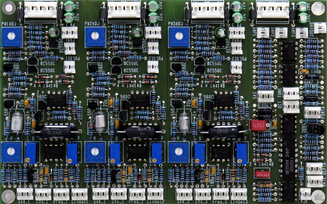
I built a Jürgen Haible Living VCO module as discussed on the Electro-Music forum. This is a very dense PCB with lots of connectors and front panel wiring.

Assembly Notes:

  1. Note that some 2 and 3 pin headers are oriented different directions. .  The three headers near each VCO power header (e.g. PW*, PWM*, and PULSE*) are rotated towards the top of the PCB.  My TUNE and OCT are rotated 180 degrees from PORTA and CVS - see next note.

  2. The reference designator image orientation for Tune and Oct is reversed from the schematics.  My connectors are mounted according to the reference designator image (the silk screen is hidden).  An earlier image of the layout showed them oriented 180 degrees.  I would rotate the connectors so they match the schematics (same orientation as the nearby CVS and PORTA connectors).

  3. The Detune controls clockwise (CW) rotation is on the left in the wiring diagram so that CW rotation will increase VCO frequency.

  4. The easiest way to make the PW adjustments is to set the Width control to mid-way (e.g. 5) and adjust R40, R80, and R120 for 50% duty cycle.  This compensates for non-linearity in the potentiometers.

  5. The MTA insulation displacement connectors in the Mouser parts have insufficient clearance for the closely spaced headers: Oct-Tune, Depth-Rate-VJK,  Amp1-Amp2-Amp3,  Pulse1-PWM1-PW1, Pulse2-PWM2-PW2, and Pulse3-PWM3-PW3.  I substituted FCI mini-latch connectors which will work with the MTA headers although the pins are 0.065" too long.

  1. Power consumption: 90 mA +15, 90 mA -15


Modification Notes:

  1. Since there is no gain adjustment for U11B and U12 I used 0.1% resistors for R137, R141, R144, and R145.

  2. I changed R3, R74, and R114 to 4.7M for the VCO fine controls.  The three MTA inputs are 1V/Oct, FM, Fine (left to right). 

  3. I eliminated R146 for a single CV input.

  4. I eliminated R138 for no master tune control

  5. I eliminated R139 and R140 for no octave select switch.  I changed C28 to a jumper to use the OCT connector for a supply link to the enhancement PCB.

  6. I changed C7, C8, C15, C16, C23, C24, C25 and C26 from 22 µF to 10 µF to lower the capacitance on the DC power connector.

  7. I added a 10K resistor from the center pin to the CW pin (ground) on the Depth control to make a semi-log response.  This gives a more natural feel to the vibrato depth.

  8. I added an  enhancement PCB to provide an LFO indicator and a three input inverting mixer for the the VCO outputs.

Living VCO Mouser part numbers  Updated

Living VCO modifications and front panel wiring


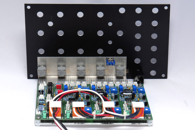
I made a bracket out of 0.050" aluminum and a daisy chain power cable to connect to the four sections.  The part numbers for the single-ended and feed-thru connectors and dust covers are in my Living VCO Mouser part number document.  The feed-thru wires are stripped in the middle where they connect to the sockets (e.g. one single length of wire with a section of insulation missing in three places).  I press the wires in and solder them to the connectors.  I piggyback another wire in the middle connector and solder it on top of the other connection.  It is tight but manageable.

Living VCO bracket drawing


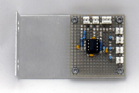
I built the enhancement PCB on a small piece of vectorboard and made a second bracket out of 0.050" aluminum.

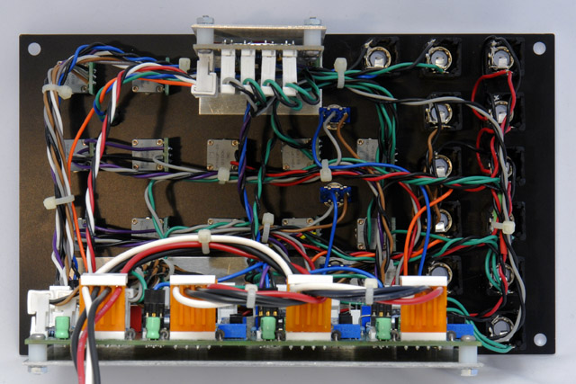
Here is the finished module with lots of panel wiring.  I really like the mixer for the three outputs.  The LFO LED would be  more useful if the brightness varied with the depth CV.


Operation

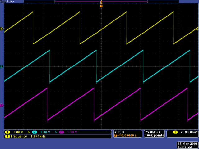
Here is a scope image of all three VCOs at 1000 Hz.  There is absolutely no indication of VCO locking.


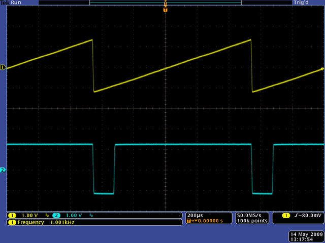
Here is a scope image of VCO-1 saw and pulse outputs.


This short video shows the operation LVCO and the stability of the three oscillators.  I operate the Detune controls and show the very fine adjustments that can be made.


Panel

I developed several front panel designs that are shown here.  I purchased a quantity of BI Technologies potentiometers so I am using Coarse and Fine controls similar to my other modules.

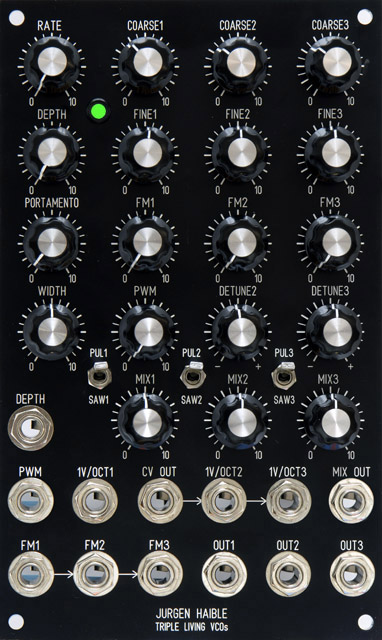
This 3U panel design features VCO controls in a vertical format.  There is a master 1V/Oct input.  The CV Out is normalled to VCO2 which is normalled to VCO3.  The FM inputs are normalled in a similar manner.  There are master Width and PWM controls and a single PWM input.  Detune controls are only used for VCO2 and VCO3.  Each VCO has a separate output and there is a mixer with individual attenuators for an inverted mix output.

Living VCO FrontPanelExpress design file


back