|
Jürgen Haible |
|
Note: The original Jürgen Haible website is no longer active but PCBs are being released at http://www.jhaible.com.
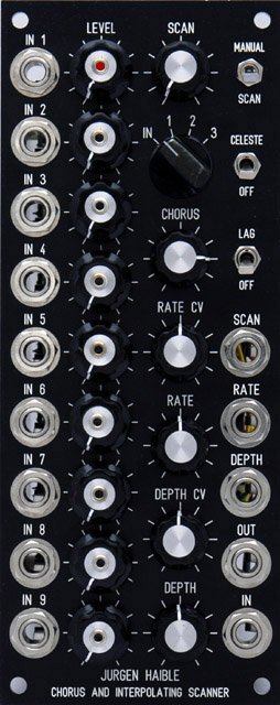
I built the Jürgen Haible Scanner Chorus/Vibrato module as discussed on the Electro-Music forum. Be sure to check out Scott Juskiw's scanner page and documentation.
This is a close-up of the back of the PCB showing 14 of the 17 soldered SMT capacitors.
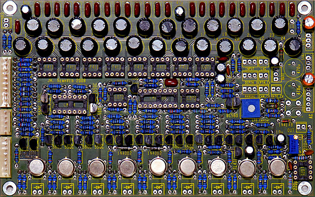
Here is the assembled PCB. I used NOS LM394 transistor pairs (across the bottom). I've since added MTA connectors for the LEDs.
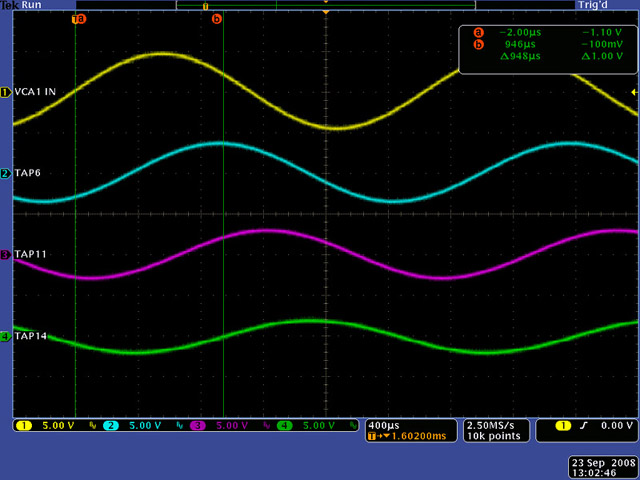
Delay Line Measurements
The scope image is a measurements through the delay line of ~440 Hz sine wave.
The yellow trace is the input (vca1_in)
The cyan trace is at 8 sections of delay (tap6)
The magenta trace is at 16 sections of delay (tap11)
The green trace is at 24 sections of delay (tap14)
The total delay, Td = [24L x 24C]1/2, calculates to be 945 µS and measures ~948 µS. Each stage contributes ~40 µS of delay so tap6 correlates to ~315 µS of delay and tap11 correlates to ~630 µS of delay.
This delay is about twice that of my 16 stage Hammond Vibrato Scanner which only uses half of the organ delay line.
An application note on passive delay lines from Rhombus Industries, Inc.
Construction
I purchased the parts kit from Tobias Schilly. The parts kit was well done. Components were grouped logically and packed in small plastic bags by type (resistors, capacitors, wires, ICs, etc). I used a Mouser 690-C4D0904N-A rotary switch for the 9P3T switch. This switch is extremely hard to turn. I had to use a flatted knob to have a good enough grip.
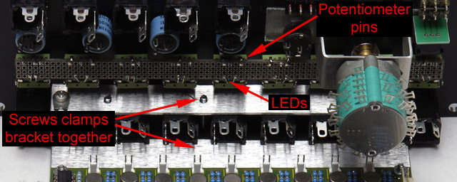
The panel is very dense and there is little room to mount a conventional PCB bracket under the controls. I fabricated a straight bracket that clamps to the 9 jacks to mount the PCB. The select switch mounts on a bracket for clearance to the nearby front panel components. A coupler and 1/4" rod extends the shaft through the front panel. A perfboard is used to fasten the fragile potentiometer pins and mount the 3 mm LEDs which illuminate the rear of the clear shafts.
Power consumption: 50 mA +15, 48 mA -15
Panel
I built the module in a 2U form factor as rack space is always limited. The vertical spacing for the knobs is similar to the Encore UEG. The LEDs are mounted behind Alpha RV141F-40E3-18BL-B100K clear-shaft potentiometers so I drilled small holes through the center of the knobs and glued in small eyelets for a finished look.
The Scan control functions as a scan cv attenuator or manual scan control determined by the switch position. This control works in parallel with the Depth control.
The rotary switch selects external inputs or one of 3 feedbacks taps. The external inputs are attenuated by individual controls and normalled to +5 volts for a default pattern generator function.
The Celeste switch adds a 0.01 uF and 2K resistor in series with R104 to mis-terminate the delay line causing reflections. I selected these values empirically.
The Chorus control replaces R103 with a 10K potentiometer to vary the amount of dry and delay signal.
The In jack is attenuated through a 220K/150K divider for 1X gain through the scanner.
|
|
Knob eyelet closeup |
Scanner FrontPanelExpress design file
This is a video showing the LEDs in operation through the clear shaft potentiometers.
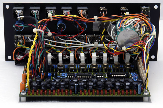
The front panel wiring is quite complex and took quite a while to solder. I had to do it in sequence starting with the perfboard, selector switch, controls, and finally the switches and jacks
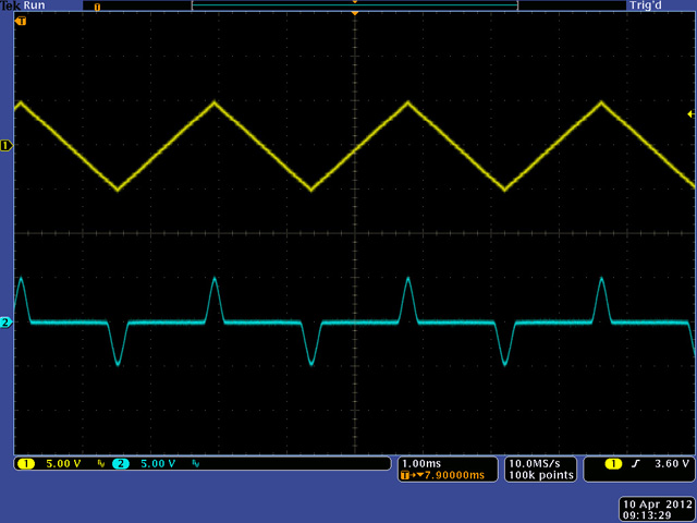
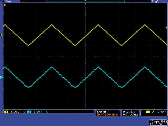
Waveshaping
The scanner can be used as a waveshaper by applying a DC level to the 9 inputs and applying the input to the Scan. I have normalled my inputs to +5 volts so with no input I can set the DC level from 0 to +5 volts. For -5 volts I need to connect the inputs to a bias generator.
In this example I have set In 1 to -5 volts and In 9 to +5 volts and am driving the Scan with a triangle waveform (yellow). The output (cyan) is a +/- 5 volt rounded pulse at the peaks of the triangle waveform.
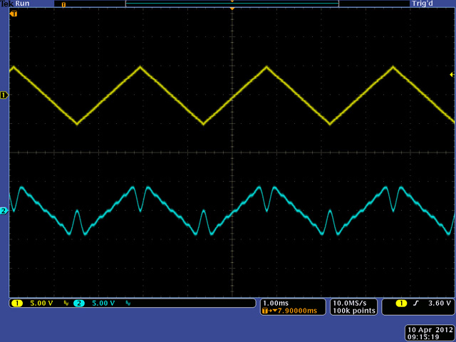
In this example I have set In 1 to 9 graduated from -5 volts to +5 volts to approximate a linear transfer function. You can see the quantization "bumps" which correspond to the DC level for that particular VCA range.
This example is the same setup except I have set In 1 and In 9 to zero to produce the notch at the peaks of the triangle.