Note: The original Jürgen Haible website is no longer
active but PCBs are being released at http://www.jhaible.com.
I built the Jürgen
Haible Frequency Shifter module as discussed in the Electro-Music
forum. I built this in a
2U MOTM format with an aluminum bracket to mount the PCBs piggyback and also
clear the various front
panel controls.
I purchased a minimum order quantity of 240 BI Technologies P260P
potentiometers to use for my projects. I like them quite well and
have some information here.
I also use the potentiometer chiclets from John Loffink.
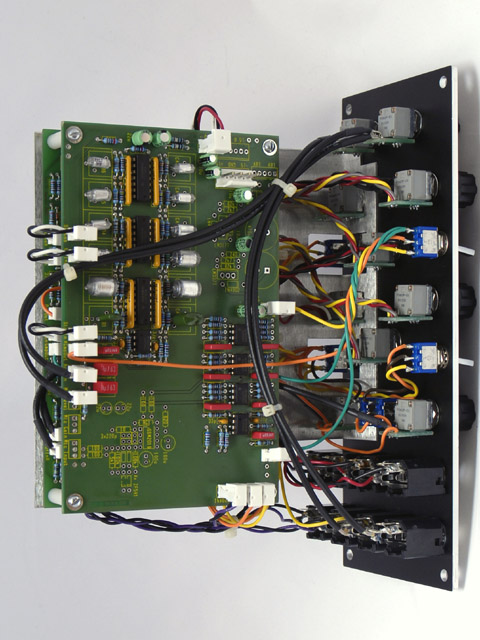
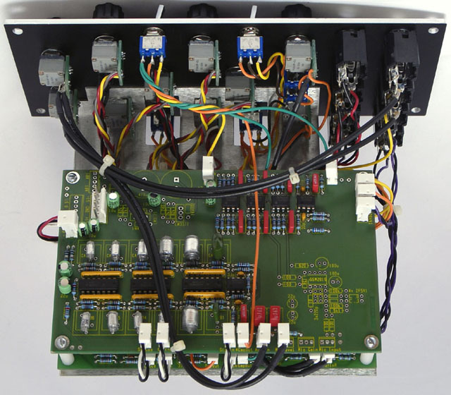
There are so many connections and calibrations for this board that I chose to use MTA connectors for all front panel controls. I chose to socket only the MC1496
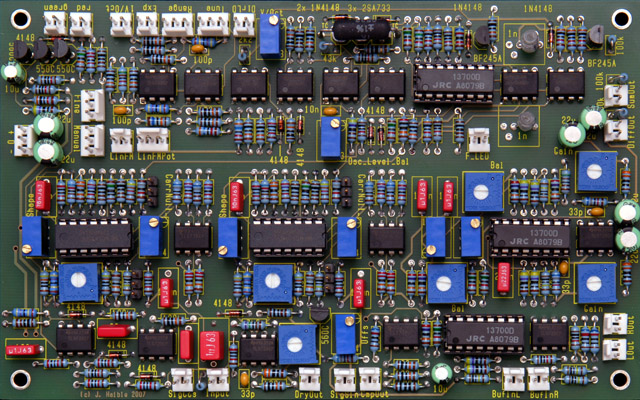
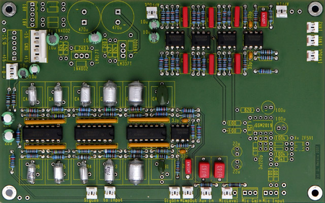
and LM13700 ICs. Here are the finished PCBs.
Construction
I only have paper copies marked up with my modifications.
They are not pretty but are available here.
|
Modification Notes:
-
I eliminated the exp polarity switch and modified the
expo cv attenuator to a reversing style. On board1 I changed R2 from
51K to 36K, added an additional
36K resistor to pin 6 of U1, and wired the attenuator similar to the linear cv control
circuit.
-
I added a separate feedback
attenuation control to pins 1 and 2 of the Mic_Level connector. The
bypass switches route the input to the respective outputs but they do not
affect the feedback control so the output may still be shifted.
-
I
changed R96 to 68K on board1 and R20 and R21 to 100K on board2 to reduce the input
gain.
-
I added an output
which adds SumOut and DiffOut by using U8A on board2. I changed R51 to
51K on board2, connected Inv1 to SumOut, Inv2 to DiffOut, and InvOut to the Out
jack.
-
I changed R46 to
510R on board1 to make the freq LED brighter.
-
The jumpers on
board1 above
R49 and R80 by the CarrNull text are not used and can be omitted.
|
Frequency Shifter
Mouser part
numbers Updated
Dome filter
capacitor values
|
Parts List and
Calibration Notes:
-
The unmarked radial mounted resistor between the SigCos and
Input connectors is R95, 1M.
-
You must slightly bend the 100K and 4.7M resistors
leads if using
MTA 0.100 for Tune and Exp connectors.
-
Most of the polyester film capacitors
in my part number list have 5 mm
spacing. These need to be bent to fit the 7.5
mm PCB footprint on several of the capacitors.
-
The 22 µF capacitors in my part
number list are slightly large and need to have the leads bent to fit the back-to-back
locations on the PCB.
-
I changed C3 and
C4 from 10 µF tantalum to 22 µF electrolytic to use with the DC power connector.
C1, C3 and C7 are in parallel (as are C2, C4, and C8) and loads the DC power
connector with 54
µF. I would recommend leaving C3 and C4 off to lower the capacitance
to 32 µF on the DC power connector.
-
There are thirty-seven 100 nF SMT capacitors, not
thirty-five.
-
The last
sentence in the 5th step of calibration should be to adjust R119
to get approx 5V pk on DiffOut, not R110.
-
Power consumption: 111 mA +15, 106 mA -15
|
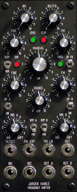
Front Panel
This design has a large manual knob and nine small knobs to fit
into a compact 2U format. I eliminated the mic input and the output level
attenuators and added a second input that is normalled to the feedback switch.
I eliminated the exp FM polarity switch by changing the exp cv attenuator to a reversing style similar to the
linear cv attenuator. Out is the mix of SumOut and DiffOut.
Frequency
Shifter FrontPanelExpress design file
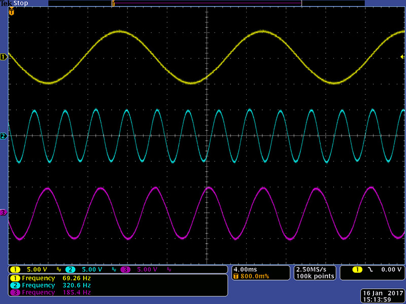
Operation
Here is a scope image showing the sum and difference with a 69
Hz sine wave. I am using my Mankato filter to generate the ~69 Hz input
sine so it should be pretty clean. The internal oscillator is running ~253
Hz so it produces a sum (cyan) of ~320 Hz and a difference (magenta) of ~185 Hz.
back
