 |
Jürgen Haible |
|
Note: The original Jürgen Haible website is no longer active but PCBs are being released at http://www.jhaible.com.
I built the Jürgen Haible Variable Slope Filter/Phaser module as discussed in the Electro-Music forum. I left off the output buffer components since I am replacing it with my modifications. Be sure to check out Scott Juskiw's varislope page and documentation.
Parts List Notes:
Assembly Notes:
|
Variable slope filter/phaser Mouser part numbers
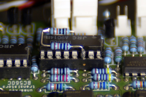
I was working on a panel when I saw the design posted by Scott Juskiw on the Yahoo ModularSynthPanels group. He included several enhancements that I liked and adopted for my module. After construction, I noticed the LFO output was 20V pk-pk. I lowered the gain of the LFO circuit to 10V pk-pk by changing R175 and R178. Since the module was already built, I added 100K resistors on U20 from pin 4 to 8 and from pin 8 to 14 to adjust R175 and R178 to the approximate values.
Scott Juskiw enhancements: (from ModularSynthPanels posting)
Varislope Modifications:
|
Variable slope filter/phase enhancements schematics (updated)
I calibrated my varislope but went back and recalibrated it again using Juskiw's very nice documentation.
I made a quick demo ... it's challenging to think, talk, twiddle, play on the keyboard, and not bump the microphone. It's not great, but it does demonstrate some of the characteristics of the filter and phaser. The patch is a saw wave input with ADSR on FM2.
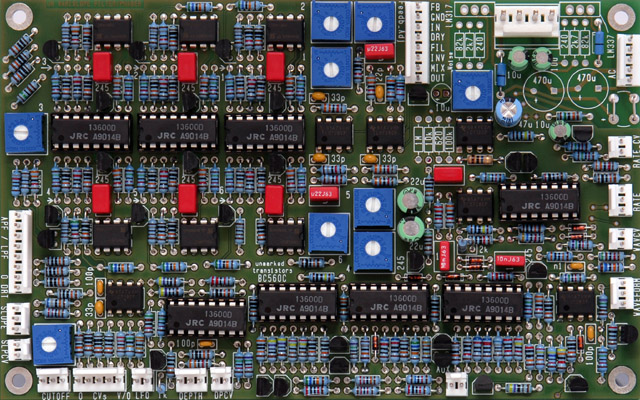
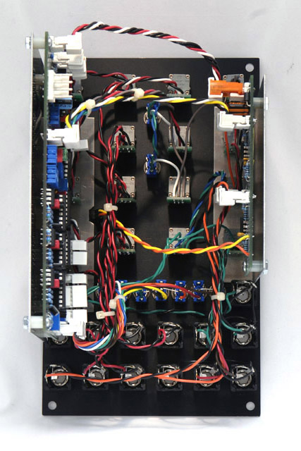
Construction
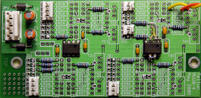
This image shows the MUUB-4 enhancements with the added op amp to buffer LFO Out.
I made aluminum brackets to mount both the Varislope and MUUB-4 PCBs. I used P260P potentiometers from BI Technologies, and potentiometer chiclets from John Loffink.
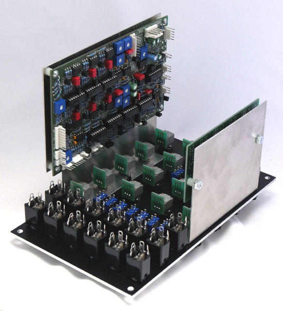
Wiring complete!
Panel
This panel is a modification of Scott Juskiw's design. I moved the switches and added nomenclature to the Wave control. To allow room for the Wave label, I rotated the control 180 degrees and made the waveform legends tangential to the tic marks.
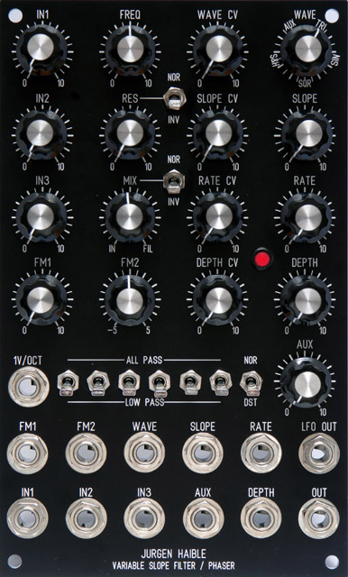
Variable slope filter/phaser FrontPanelExpress design file (updated)