|
DJB- Kurzweil Keyboard Conversion Project |
|
This page describes my latest DIY keyboard project. I purchased all of the electronics for a Kurzweil Ensemble Grand Mark III digital piano off of Craigslist for $5. The piano no longer worked and the owner wanted to reuse the cabinet so I bought all of the 'guts'. From the date code on the ICs, this piano appears to be circa 1988.
Kurzweil graciously provided most of the schematics but I was unable to repair it. The 68000 microprocessor 'hung' whenever accessing the proprietary 'Arnold' sound chips. I was unable to locate any information on diagnostics and the schematics were incomplete in this area. Here's all of the parts spread out on my bench.
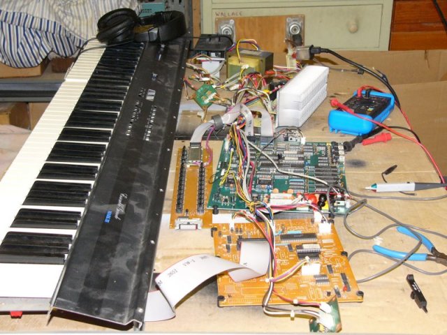
All of the electronics operated except for the main PCB (large green). I have a functional 4 channel power amplifier, 88 note weighted keyboard, and a keyboard controller. Not bad for $5!
I decided to build a MIDI keyboard and started to design my own controller. Interestingly, the keyboard controller interfaces to the main controller via 2 wire serial. Could this be MIDI? Running an external power supply I was able to verify that the keyboard controller does indeed output MIDI on channel 1. This controller interfaces to the keyboard and provides velocity and has interfaces for the pitch and modulation wheels, sustain and soft pedals, and a general purpose slider and a key transpose swtich. Interestingly, it appears that this controller has lots more functionality as the pcb is only partially 'stuffed'. I imagine that it might have MIDI channel jumpers but I am unable to find any useful information beyond basic schematics.
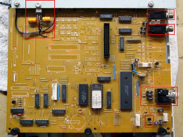
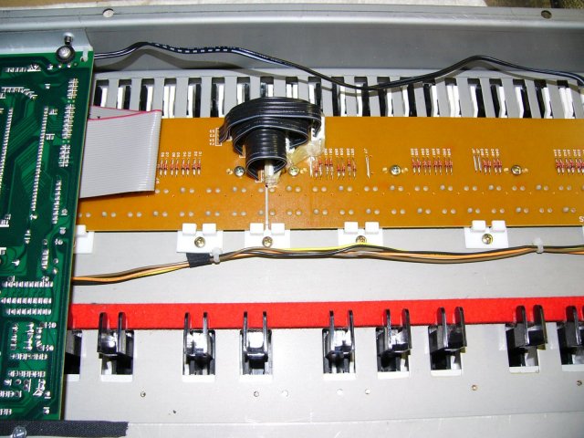
There were 'unstuffed' part locations for a MIDI out jack and two 1/4" pedal jacks. I took these parts from the main controller and traced out the unused circuitry which implemented an emitter follower to buffer MIDI out. I decided to not use the key transpose switch (later determined to be a bad decision) nor the general purpose MIDI slider. I did add a +5 volt regulator on the board so I could power this with a 9 volt DC power supply. This gives me a fully functional MIDI keyboard controller. Here is a photo of the completed pcb with the parts I added outlined in red.
I have no idea where this board mounted in the original cabinet. It is pretty large and I want my cabinet to be as small as possible. I determined that I could mount the PCB upside down in the cavity of the keyboard. I needed to make a bracket to mount one side of the PCB. Here is a photo of the controller mounted in the keyboard chassis.
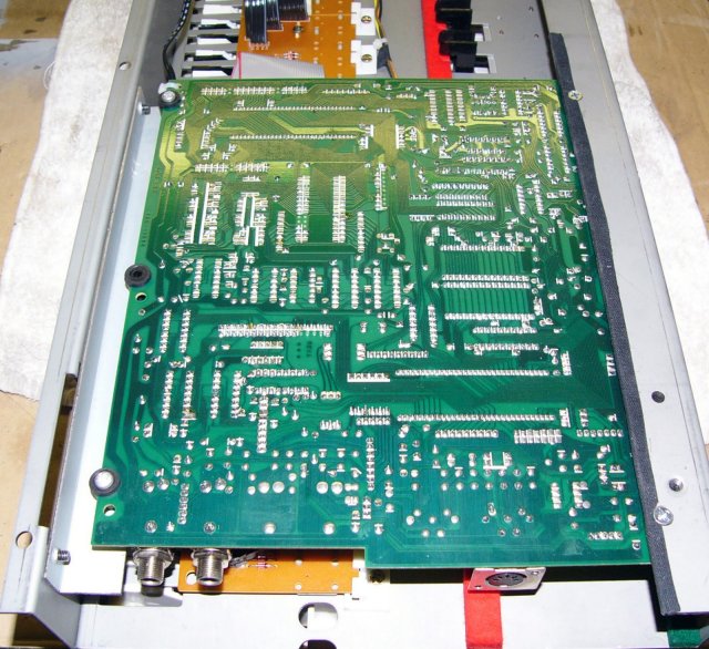
I ran the cables for power (upper black) and for the modulation and pitch wheels (middle) across the keyboard. This is a heavy and well built keyboard!
Cabinet Design and Construction
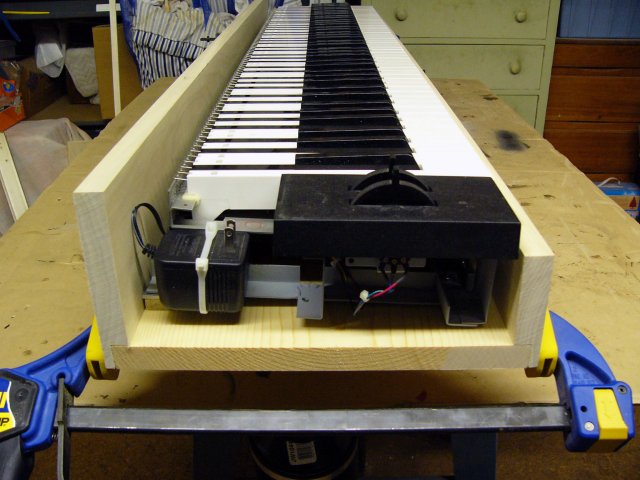
I designed two small FrontPanelExpress panels for the keyboard - one for mains power, fuse and switch, and the other for MIDI and pedal jacks. I used an internal 9 volt DC wall wart power supply for the keyboard controller as it only draws 170 mA. I built a cabinet from poplar with a pine bottom. In the photo I have the main portion assembled with a 1/2" riser at the rear to level the keyboard to a horizontal position. I welded a small frame to attach the pitch bend and modulation wheel module to the keyboard and also support the internal power supply.
Cabinet Assembly
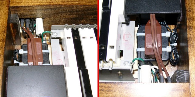
The photo on the left shows the rear panel power panel with IEC connector, fuse, and power switch which connects to the internal power supply. The photo on the right shows how the power supply mounts behind the pitch bend and modulation wheel assembly.
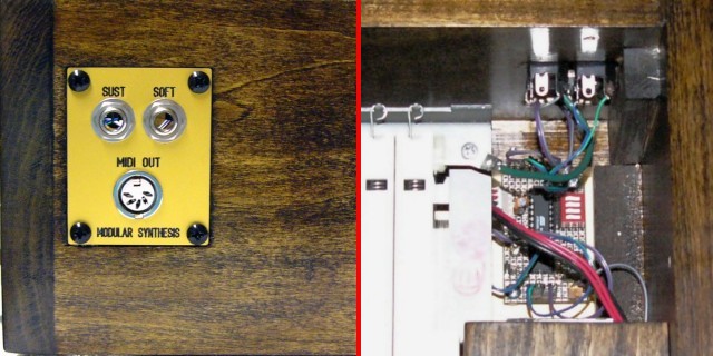
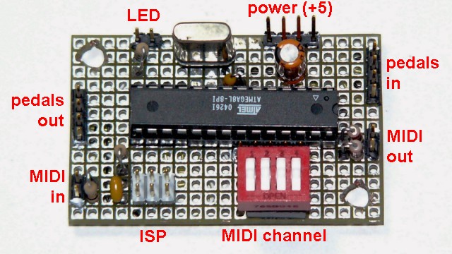
The photo on the left show the rear jack panel which is set flush into the cabinet. Inside on the right is a small microcontroller board which processes MIDI and pedal signals. I used an Atmel ATMEGA8 microcontroller. This controller inverts the pedal signals to use normally-open pedals and transposes the keyboard by 5 semitones. It also replaces the MIDI channel information with the DIP switch selection. The LED provides a power-on indication and blinks briefly for each key depression.
MIDI FrontPanelExpress design file
Power FrontPanelExpress design file
Here is a close-up photo of the microcontroller board - not many parts for a complete MIDI data processor! Why the transpose of 5? The Kurzweil keyboard had a MIDI transpose switch and a general purpose slider that I did not install. I did not check the MIDI codes and with the switch disconnected the keyboard was transposed to the key of G. I did not notice this until the keyboard was completed. While I could have disassembled the keyboard and added jumpers, I also wanted to inhibit the general purpose slider message that is sent on power up and also provide capability for setting the MIDI channel. The 6 pin header is for programming the microcontroller.
DJB-Keyboard software source code
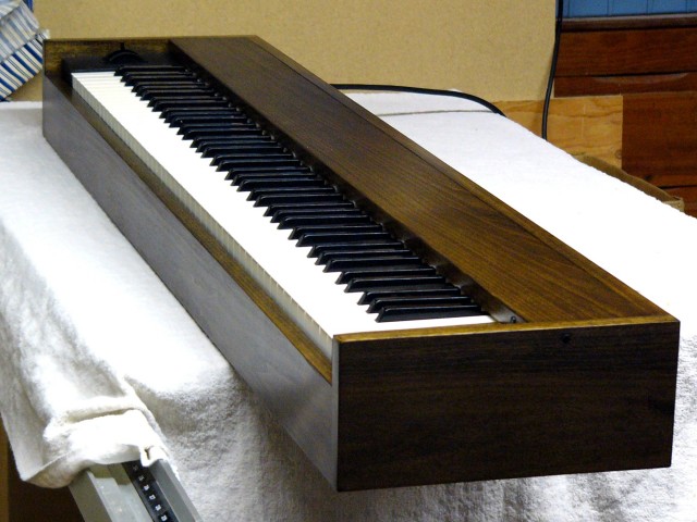
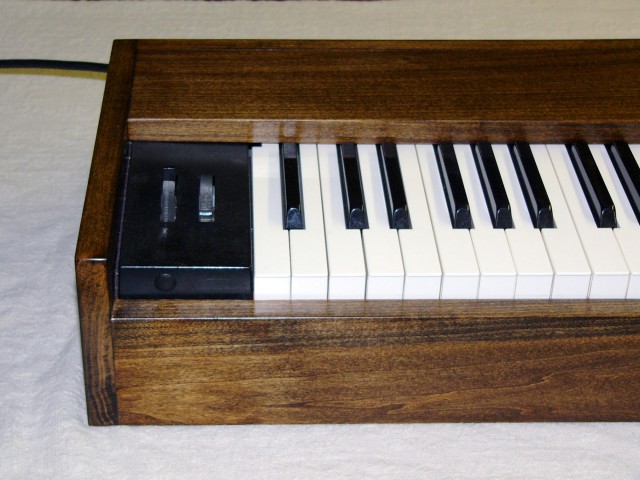
Here is the completed keyboard left side showing the pitch bend and modulation wheel panel. This keyboard is so long it is hard to photograph.
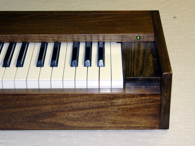
Here is the keyboard right side showing the right cheek block and LED light.
And here is the finished project! This keyboard is now dedicated to my MOTM-650.