 |
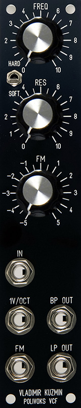
Polivoks VCF |
|
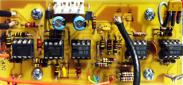
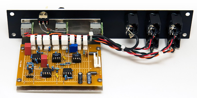
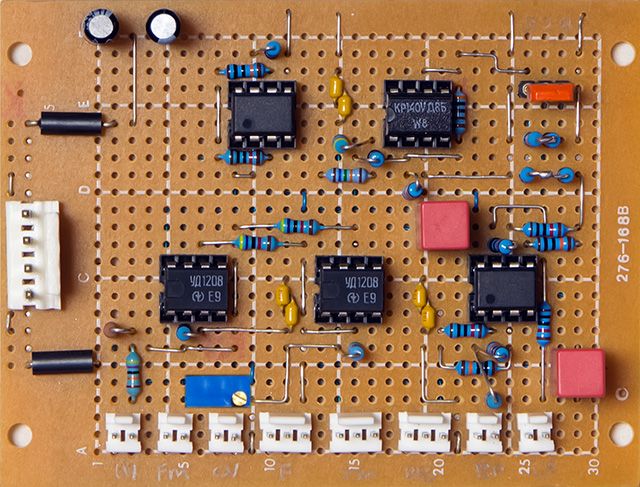
I repaired a Polivoks filter and was intrigued by the use of programmable op-amps for the filter cell. The Polivoks filter is derived from the Polivoks synthesizer designed in the early 1980s and uses the Russian K140УД12 programmable op-amp which is equivalent to the obsolete uA776. There are at least three Electro-Music forum postings on the Polivoks filter Polivoks Filter, Building The Polivoks Filter, Polivoks VCF Simple Schematic Layout, and a Muffwiggler forum on Papareil Polivoks Filter Support Thread. There is also an interview with Vladimir Kuzmin from the Urals Vector Company on the Polivoks synthesizer. This is the Marc Bareille Polivoks filter PCB I repaired which used the Russian УД1208 and KP140УД85 op-amps and the KT315Г transistor.
Construction
I decided to build this filter and try the NTE888M replacement for the uA776 which is available and less than $2 from a couple of suppliers on Amazon or you can use the distributor locator on the NTE website. The NTE webstore is www.ntepartsdirect.com but for some reason they don't list the NTE888M.
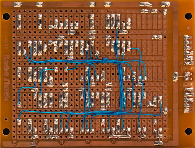
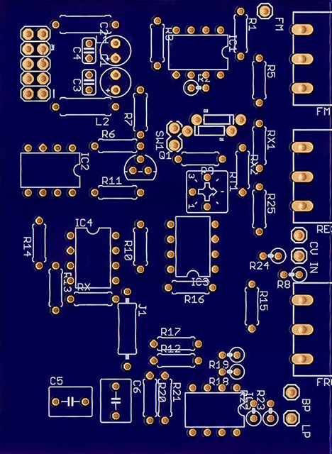
I looked at the Marc Bareille Polivoks PCB but decided to just hand wire a proto board since I didn't know how the NTE888M would perform. Since I did this module there is another PCB available at the topic [ORDER] Polivoks VCF clone kit on the Muffwiggler forum.
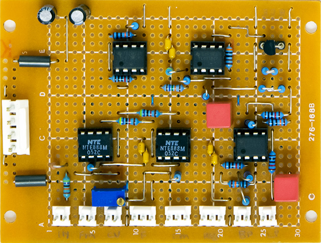
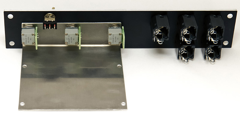
I custom build my brackets out of 0.050" aluminum so they fit the panel and PCB perfectly.
Modifications
I made a few modifications to Marc's schematics. There is a lot of discussion on the forum about changing the low end of the CV range. As designed the frequency control varies the Iset current from 0.2 µA to 13.76 µA while the FM control with a 5V input will decrease the current all the way to 0. As mentioned in the forums the frequency control will not completely cut off the filter. I found that the suggestion of connecting the frequency control to -15V instead of ground extends the range too much and results in a large dead zone at the bottom end of the control. I added a 47K resistor between the frequency control and -15V which sets the control span to -5V to +15V for a usable frequency control range.
The CV input was considerably off from 1V/octave. With a 100K R9 the frequency change was about 1V/20 semitones, or ~3.2x instead of 2x. Changing R9 to 175K was very close to 1V/octave for the NTE888M parts. I added a 100K trimmer in series with R9 and could trim the filter to 1V/octave. The FM control has a very wide range with R5 at 47K so I increased R5 to 120K.
Power consumption with the NTE888M parts measured 10 mA on both the +15V and -15V supplies.
Modified Marc Bareille schematic (my modifications outlined in red) updated 3-11-13
An fellow synth enthusiast designed a PCB from my modified schematics and sent me one - Thanks!
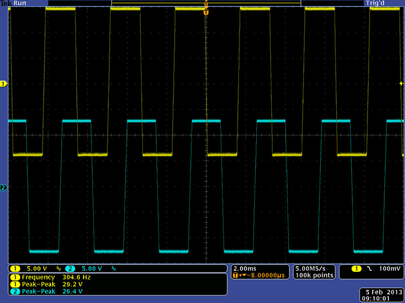
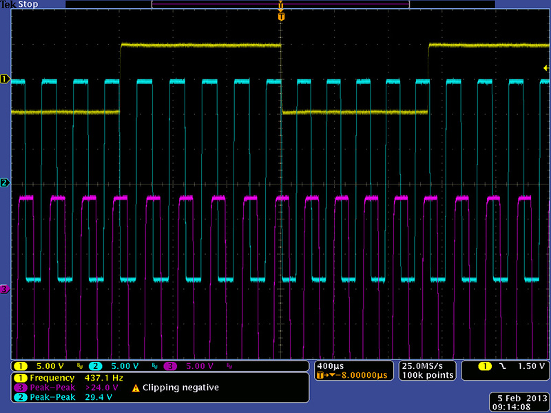
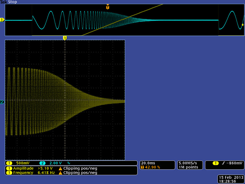
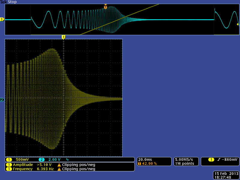
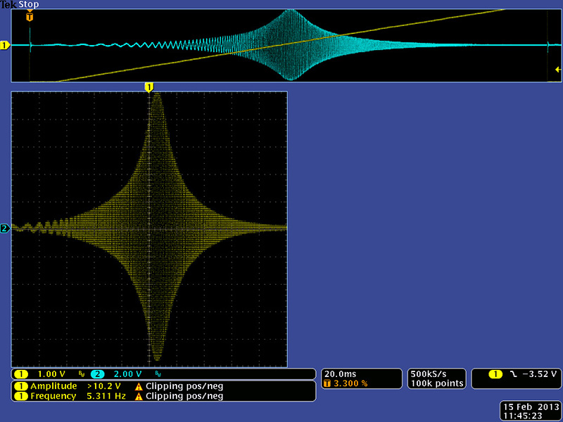
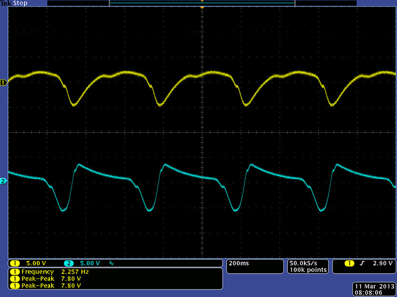
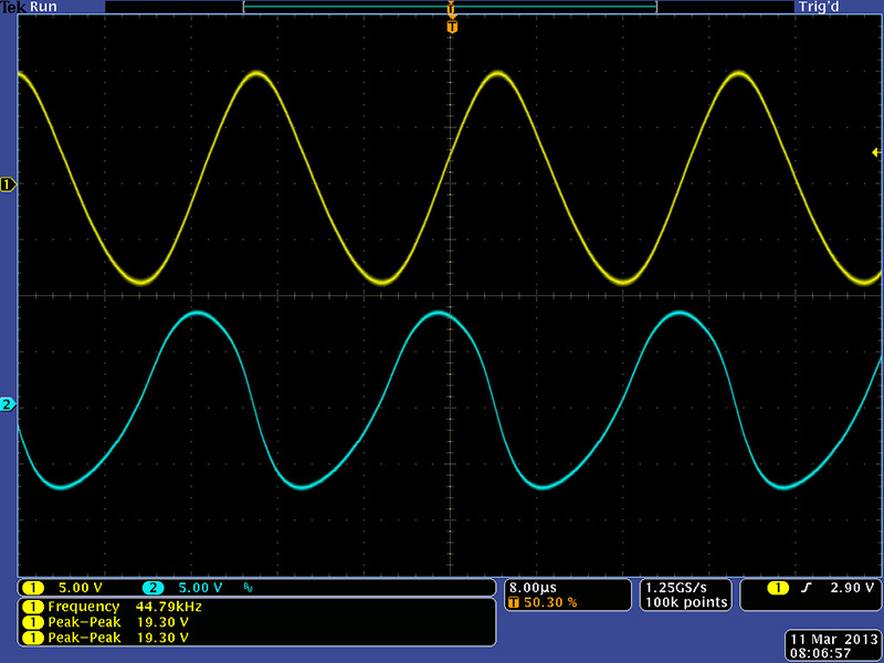
The self-resonance was a rail to rail square wave as shown in this scope image.
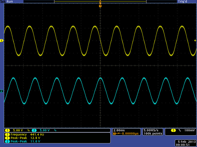
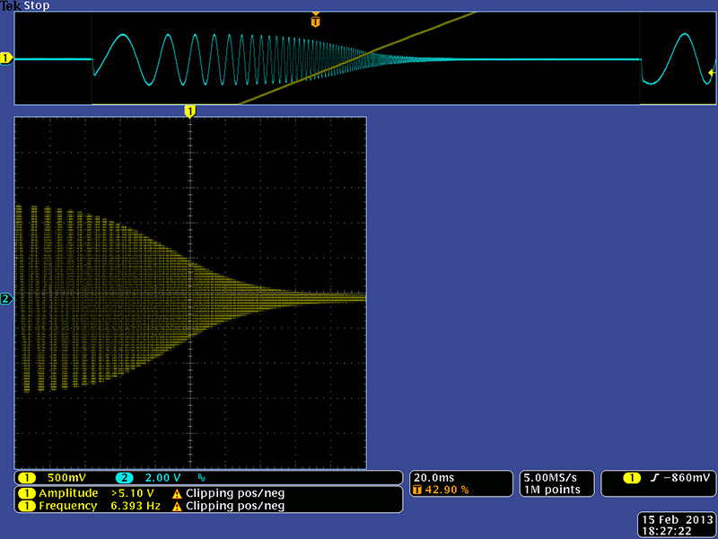
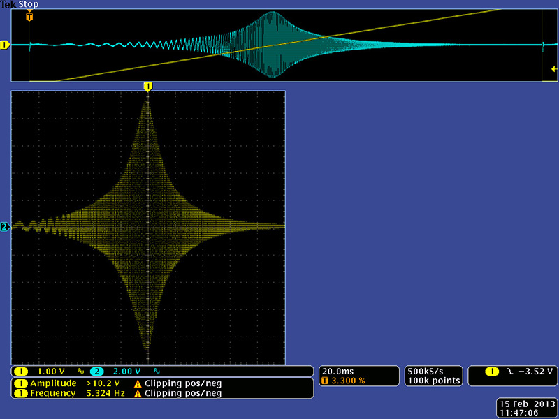
I don't like module outputs going rail to rail so I tried various schemes to limit the output of U3 in self-resonance. I found I could use the current limiting feature of the programmable op-amp with clamping diodes at the output of U3 to ground. I could considerably improve the output to a sine wave by adding a 100R resistor between pin 3 of the resonance control and ground and connecting the clamping diodes with a 470R series resistor between pins 1 and 2 of the resonance control. I added a switch to select "hard" or "soft" resonance. The "soft" limiting increases the self-resonance frequency a bit.
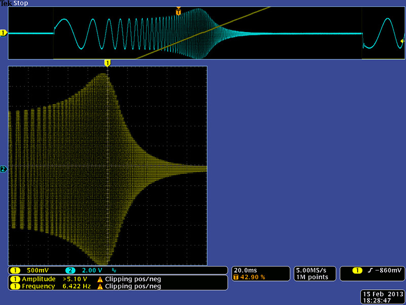
This image shows the original resonance with a square wave input. The output is rail to rail and the self-resonance totally swamps out the square wave input.
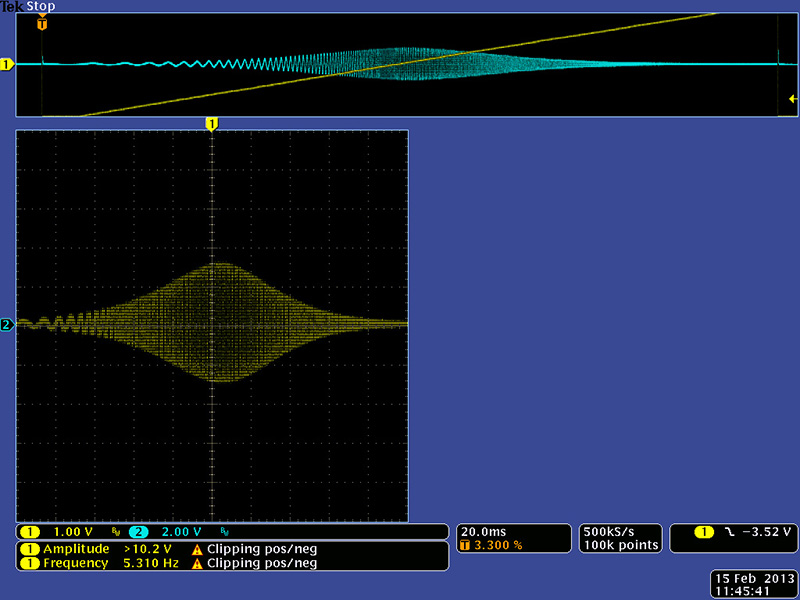
With the clamping diodes the output is more well behaved with lots of ringing on the band pass and low pass outputs. The resonance makes the output pretty hot but not to the rails. This is reasonably well behaved and so will operate without an input attenuator to keep it to a 3 large knob 1U panel.
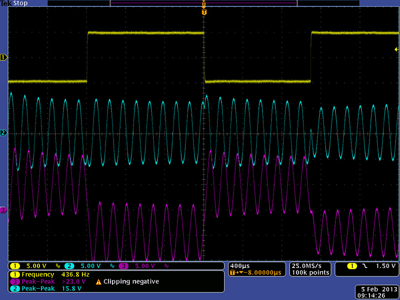
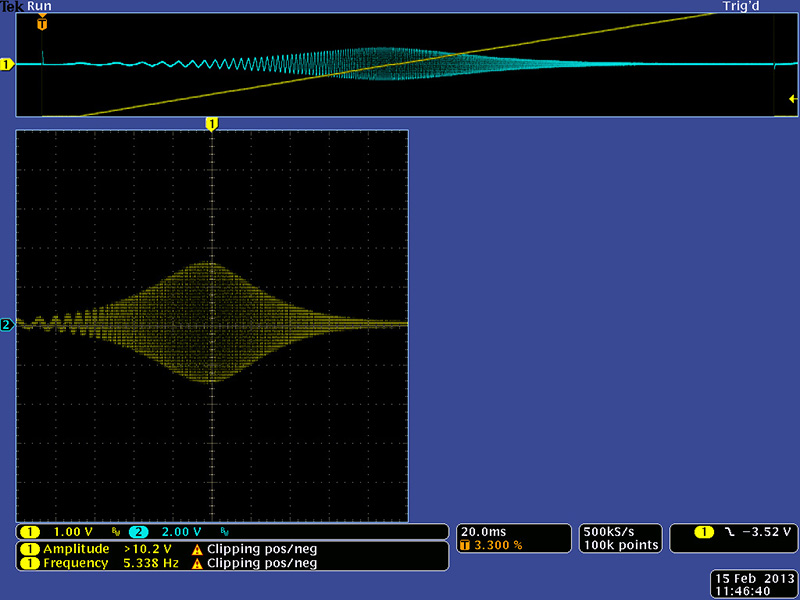
This filter does need input attenuation as the output levels are way too hot. I modified R24 to 470K which drops the filter at about unity gain with the NTE888M parts. This image shows the band pass and low pass outputs with no resonance and a 10V pk-pk square wave input.
Adding resonance increases the output up to nearly 20V pk-pk which is on par with other filters. The input attenuation level works well for reasonable performance.
Filter Response Curves
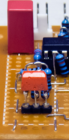
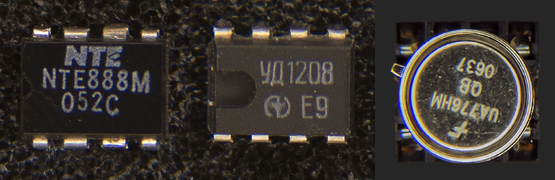
I obtained the Russian УД1208 and KP140УД85 op-amps and the KT315Г transistor. I used sockets for the op-amps and transistor so I could swap the NTE888M, TL071 and 2N3904 with the УД1208 and KP140УД85 op-amps and the KT315Г transistor to compare performance. The KT315Г transistor has flat leads so I soldered small wires to the leads to fit the socket.
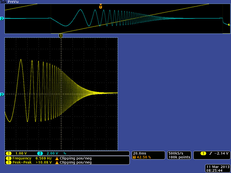
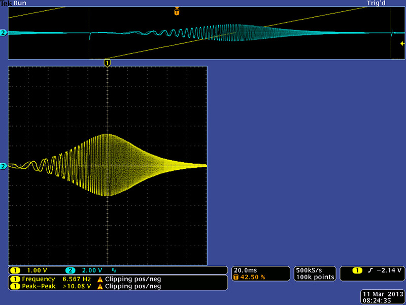
I used an XY oscilloscope display to display a frequency response curve for low pass and band pass with and without resonance (the TL071 and 2N3904 parts were installed for these XY measurements). Originally I saw a DC shift in the output at the higher frequencies but this was due to the output of my VCO at those frequencies. I tried different VCOs until I had a good frequency sweep output with no amplitude or DC shift to use for these XY measurements.
The NTE888M low pass output.
The УД1208 low pass output looks basically identical but has bit lower cutoff frequency.
The NTE888M low pass output with some resonance.
The УД1208 low pass output with the same resonance setting. The lower cutoff frequency is easier to see with the peaked response. The output is also lower in amplitude.
The NTE888M band pass output.
The УД1208 band pass output with a bit lower center frequency.
The NTE888M band pass output with some resonance.
The УД1208 band pass output with the same resonance setting. The lower center frequency is easier to see with the peaked response.
I compared these last two frequency response curves by inverting the NTE888M frequency response curve and adding it to the УД1208 frequency response curve (identical colors when inverted and added form 50% gray). The resulting image shows the frequency and amplitude differences between the two parts. The УД1208 output is the cyan and yellow traces and the NTE888M output is the red and blue traces. You can also see the differences in the ramp frequency second and third decimal point values and also the timestamp seconds.
_(nte888m-b).jpg)
The NTE888M and the УД1208 parts work equally well in this filter. The NTE888 parts have slightly more gain. The cutoff and center frequency shift is probably either due to a slightly different Iset control response curve or Vbe differences in the Iset pin input.
Min & Max Self-Oscillation
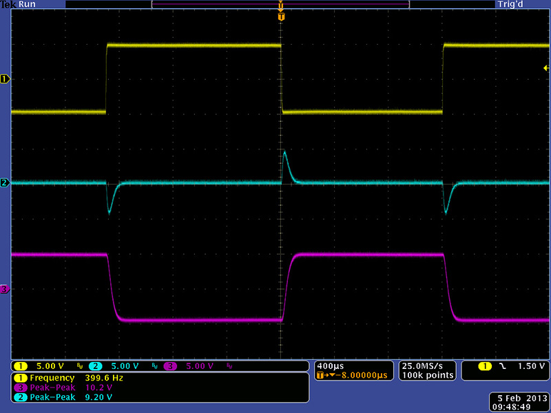
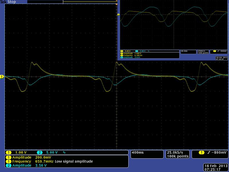
I measured the minimum resonance using the frequency control with the NTE888M and the УД1208 parts with the soft limiting (the KP140УД85 and KT315Г parts were installed for these min and max measurements). Both parts show crossover distortion at low frequencies and the УД1208 parts exhibited the same shift to lower frequencies but the output amplitude was now greater. The noticeable flattening of the УД1208 low pass output diminishes by about 220Hz. Changing the KP140УД85 and KT315Г to a TL071 and 2N3904 increased the NTE888M minimum frequency 1.15% to 110 Hz. Adding the 47K resistor mod to the frequency control lowers the minimum self-oscillation for the NTE888M from 95 Hz to ~2 Hz.
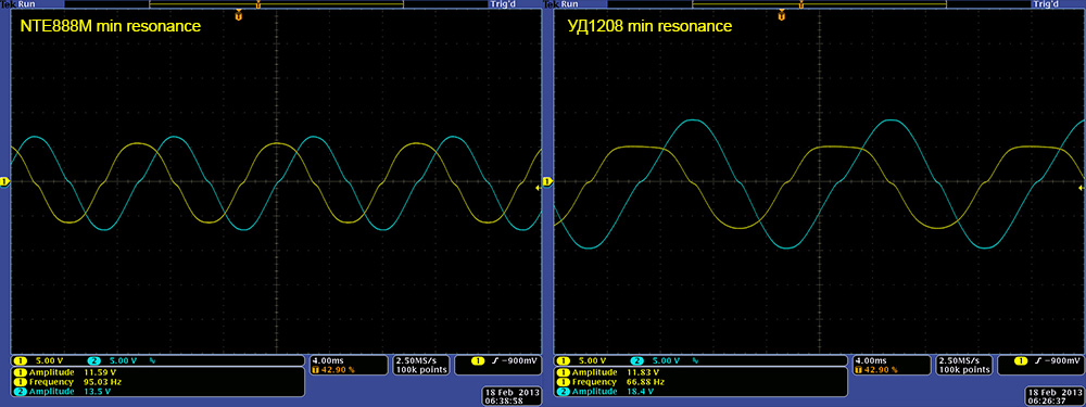
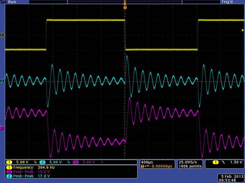
Using external CV I could lower the minimum frequency quite a bit further. The NTE888M parts would self-oscillate down to below 2 Hz with significantly distorted waveforms. The higher frequency ripples diminished at just over 6 Hz although a later measurement did not show them at all.
The УД1208 parts would also self-oscillate down to below 2 Hz with significantly distorted waveforms but much lower output amplitude (scope set to 1V/Div). They also exhibited the higher frequency ripples which diminished also at just over 6 Hz.
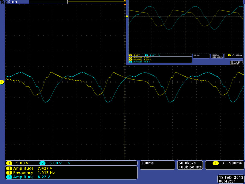
This image shows the maximum resonance using the frequency control with the NTE888M and the УД1208 parts with the soft limiting. The УД1208 parts exhibited the same shift to lower frequencies and lower amplitude. Changing the KP140УД85 and KT315Г to a TL071 and 2N3904 decreased the NTE888M maximum frequency 1% to 51.4 KHz.
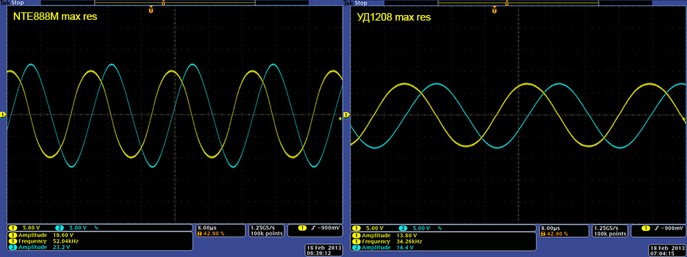
The NTE888M and the УД1208 parts self-oscillate equally well over a usable audio frequency range. The NTE888 parts have slightly better waveforms but the Polivoks filter was well know for distorted, dirty and gritty behavior.
uA776 Performance
I received my uA776 about a month after the prior tests. I didn't keep the control and all oscilloscope settings from those tests so I couldn't do an exact comparison to the NTE888M and УД1208 op-amps.
The uA776 operated in self-resonance over a range similar to the NTE888M with a low frequency around 2 Hz.
This image shows the uA776 maximum resonance using the frequency control with soft limiting. It is not quite as high as the NTE888M parts but the band pass begins to show distortion.
Both the low pass and band pass response curves look similar to the NTE888m and УД1208 op-amps.
My summary is that the NTE888M, УД1208 , and uA776 op-amps all perform reasonably well. There are minor differences in maximum frequency and amplitude. The NTE888M seems to have a slight edge in "cleaner" waveforms but use whatever parts you can obtain and enjoy this filter.
Filter Operation
All of these demo files are with the NTE888M op-amps. Here is a short video of the hard and soft self-resonance with no audio input and hard and soft resonance on the low pass and band pass outputs.
This wave file demonstrates the self-oscillation tracking using soft resonance. There is a lot of drift with the Polivoks filter but it is more stable as it warms up and for short periods of time. The right channel is a MOTM-300 and the left channel is the Polivoks LP output. It tracks pretty well.
This wave file demonstrates the LP output. The MOTM-300 is driving the Polivoks filter with an AR generator into the FM input. I sweep the frequency, soft resonance, hard resonance, and FM input controls. You can hear the hard resonance break into clipping around 0:49 and again at 1:50.
| Polivoks low pass filter demo wave file |
This wave file demonstrates the BP output. The MOTM-300 is driving the Polivoks filter with an AR generator into the FM input. I sweep the frequency, soft resonance, hard resonance, and FM input controls. You can hear the hard resonance starting to clip around 0:38 and break into clipping at 0:50.
| Polivoks band pass filter demo wave file |
This wave file demonstrates the the filter's grunge factor. I used the Circle Machine to drive a MOTM-300 and took a quick video of the Circle Machine in action.
The first part is the MOTM-300 driving the Polivoks filter with an E580 mini-sampling delay slightly delaying one channel. The second part I add slight FM modulation of the filter by a fast LFO and adjust the hard resonance to nearly full. This filter can get pretty grungy. I normalized the volume level of the first part to match the overdriven level of the second part. Remember on the second part you are mostly listening to the hard resonance being driven by the sequencer CV.
| Polivoks grunge demo wave file |
Panel Design
I built this in a 1U three knob MOTM-style panel with the resonance "soft" limiting switch.
DJB-Polivoks FrontPanelExpress design file