|
Buchla Pulser PCB |
|
I built the Aaron Lanterman adaptation of the Buchla Music Easel Pulser. Aaron's information on the PCB is on his Lantertronics Pulser page.
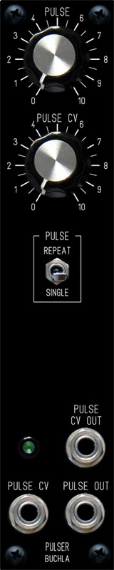
The Pulser outputs a pulse and sawtooth (downward ramp) waveform in either a single or continuous mode initiated by a SPDT center-off switch. The CV Out is 0 to 13.5 volt waveform which goes high as the switch is pressed and the sawtooth begins when the switch is released. The Pulse Out is a narrow 13.5 volt pulse coincident with the start (vertical portion) of the sawtooth waveform. I bought the Rev 1 PCB which corrects several of the Rev 0 issues.
Pulser Rev 1 Schematic (updated and published with permission from the Aaron Lanterman site) Updated
Pulser Rev 1 Mouser Parts List
I found a couple of component value and silk screen errors on the Rev 1 PCB which I added to Aaron's documentation.
Pulser Rev 1 Updated Documentation (published with permission from the Aaron Lanterman site) Updated
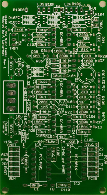
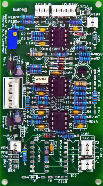
Pulser Rev 1 Components (corrected silk screen errors)
I updated the schematics with my modifications and indicated the parts not used.
Pulser Rev 1 schematics with modifications Updated
Modifications
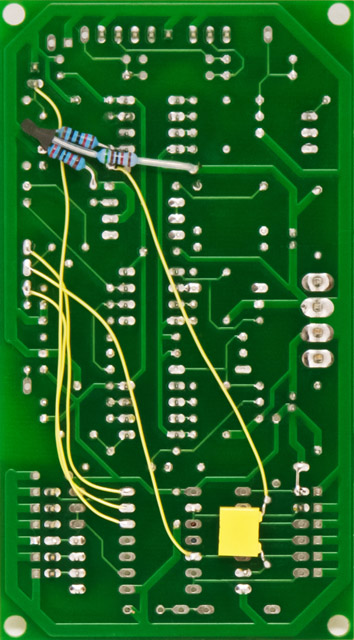
I did not install the 4001 and 4016. I initially used the inverter with modifications to replace the 4001 for the PPA and FB outputs. My Pulser would not self-start in continuous mode so I had to start by pressing single and then switching to continuous (this might be a side effect of eliminating the 4001). Another anomaly was that the narrow FB pulse would not enable the sawtooth to fully reach 13.5 volts at the higher frequencies so the amplitude would change with frequency. I installed D1 and C110 to widen the pulse to eliminate this issue. I decided to redesign the pulse output circuitry to increase the Pulse Out to 5 mS which is what I use for triggers. This wider pulse also eliminated the need for D1 and C110. With these modifications the module would now self-start in continuous mode.
|
Pulser Modifications: All modifications are detailed on schematics with modifications (see below) PCVA
changed to 5 volt output: PPA
changed to 5 mS 5 volt output: LIN
changed to 5 volt input: LOS
changed for 100K potentiometer LAMP: Other: |
I used the pads for the 4001 and 4016 to mount the additional MTA connectors for the LED, switch, and CV Out. The attenuation resistors are wired on the output jacks.
Waveforms
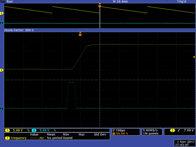
This image shows the 50 µS unmodified Pulse Out.
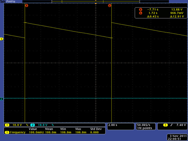
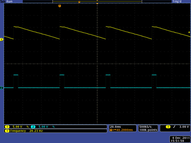
This image shows the minimum frequency. I calibrated the Trim for 0.1 Hz to 100Hz operation. These waveforms are pre-attenuation so they are 13.5 volt outputs.
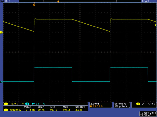
This image show the maximum frequency and you can see the 5 mS Pulse Out. Note that there is a 5 mS flatten portion of the sawtooth waveform as it starts at the end of the Pulse Out. These waveforms are pre-attenuation so they are 13.5 volt outputs.
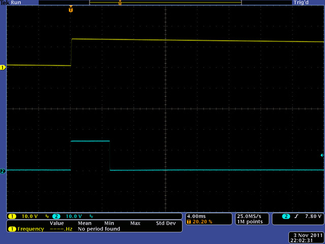
This image shows a longer period where the 5mS flatten beginning becomes negligible. These waveforms are pre-attenuation so they are 13.5 volt outputs.
This image shows the attenuated 5 volt outputs.
Panel
My initial concept was a 1U panel using standard MOTM knobs and spacing. I decided to combine the Pulser with the Timbre Generator and Crossfader in a single 2U module.