 |
Magic Smoke Electronics |
|
This page describes my evaluation the new Magic Smoke Electronics Thomas Henry TH-301 LFO. There are a few modifications required for the Rev1 PCB and I came up with a few of my own.
| Rev1 PCB modifications are documented here. |
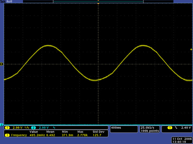
I used a 2 µF timing capacitor for the 8038 which produced a frequency range of 0.5 Hz to 160 Hz. The sine wave holds it's shape to 0.5 Hz although the amplitude drops off below 1 Hz. The triangle and ramp hold a reasonable shape to about 1 Hz and then deteriorate and the amplitude decreases below 1 Hz. Here is a 0.5 Hz sine wave with amplitude about +/- 3 volts. The Rev2 PCB adds a second capacitor and a hi/lo frequency switch.
Calibration
The first adjustment is the symmetry and offset using a 10 Hz triangle wave.
The second adjustment is the sine distortion for best symmetry and offset.
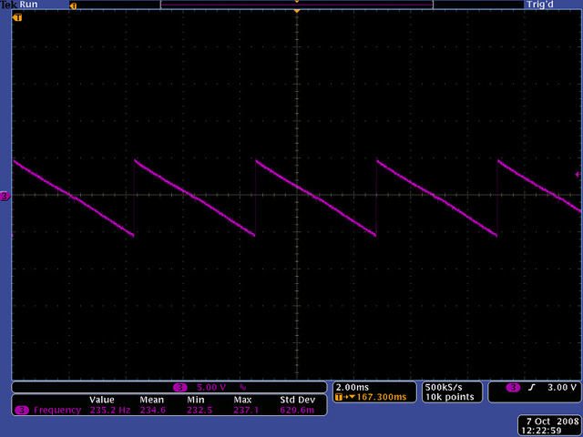
The third adjustment is the ramp connect for a nice smooth waveform.
The fourth adjustment is an output offset. Adjust the trimmer so the positive and negative peaks are equal. The sine, triangle, and ramp waveforms all had different offsets. I adjusted the trimmer using the triangle output.
The last adjustment is the volts/octave trim and the LFO temperature must be stable. I used my keyboard as the voltage reference and disconnected the coarse and fine controls so 0 volts input would have 0 volts on the trimmer. That way I could measure the base frequency at 0 volts and adjust the trimmer for 2X the frequency with 1 volt input. Then I checked and adjusted the trimmer for 4X the frequency with 2 volts input and 8X the frequency with 3 volts input.