 |
Magic Smoke Electronics |
|
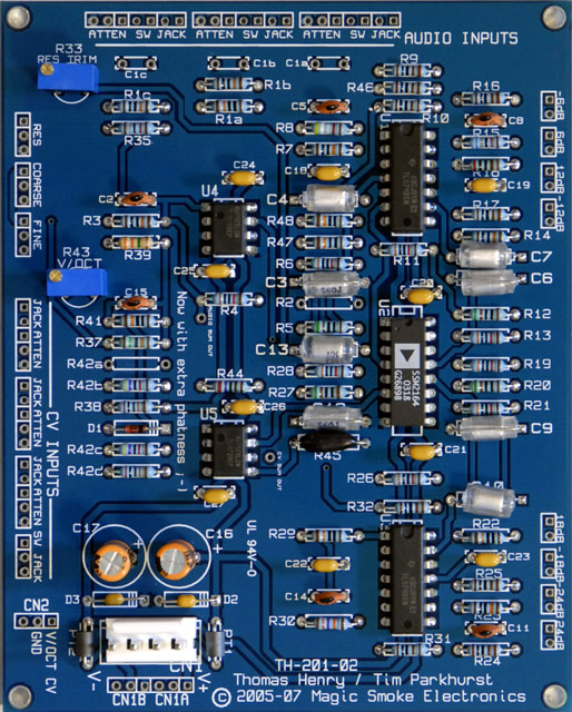
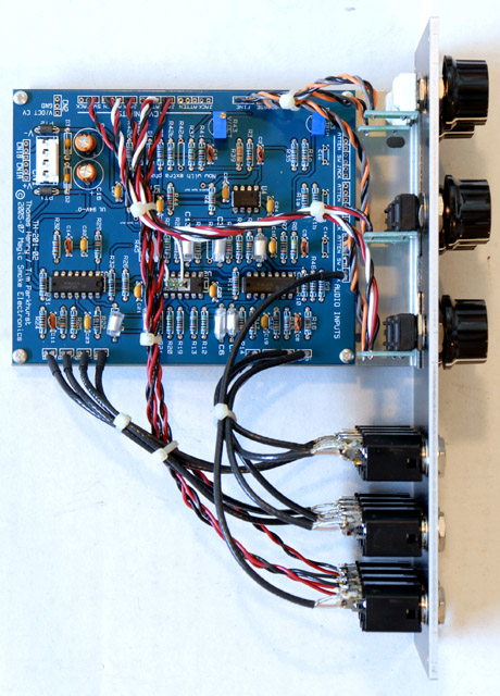
I built a Mankato filter module with a Magic Smoke Electronics rev2 PCB as discussed on the Electro-Music forum.
Digikey sells 3300PPM 5% 0805 SMD tempco resistors for about $0.55 each. I made my through-hole 2K tempco by soldering together two 1K 3300PPM SMT tempco resistors and encapsulating them in epoxy. I mounted one lead in my variable speed drill and rotated it slowly while layering fast setting epoxy on the resistors. This shaped the epoxy into a nice elliptical shape. Part numbers are on my parts and construction page.
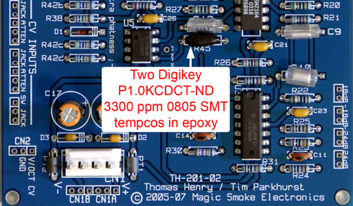
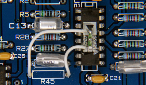
The SSM2164 has a reasonable amount of self-heating and there is a temperature difference between it and the location of R45. I decided to mounted the SMT tempcos directly to the SSM2164 with a small amount of epoxy and wires connecting to the PCB. I've mixed the output of this filter with my A-440 oscillator and have listened to a steady beat frequency for over an hour. There is a slight drift in the first few minutes and then it is pretty solid. I changed the Coarse and Fine potentiometers from conductive plastic to cermet to improve temperature stability.
Note: The SSM2164 quad VCA exhibits a catastrophic failure mode when the V+ pin is powered and the V- pin is disconnected (e.g. disconnected means open, not at ground potential). There is documentation on this failure mode on Neil's Webbly World page. The modification to prevent this failure is to add a schottky diode with the anode connected to pin 9 (e.g. -15 volts) and the cathode connected to ground to provide a path for current to flow the negative supply is disconnected. The Mankato filter already has diode D3 wired this way for reverse voltage protection. All you need to do is change D3 (and D2) from a 1N4002 to a schottky 1N5817. (If you have a sharp eye, you will note that I did not install these diodes but rather used ferrite beads for PT1 and PT2 and 0.1 uF decoupling capacitors for D2 and D3; hence my filter is not protected.)
Panel Design
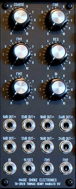
Since this module self-resonates and goes to low frequencies, I want to have all 8 outputs. Here is a my final 2U panel design with standard knob and jack spacing. There is only a single audio input and attenuator. I tried a number of alternative panel designs with closer jack spacing, smaller UEG-style knobs, and a 3U design before deciding on this panel design.
TH-201/8 Mankato VCF FrontPanelExpress design file
I assembled the module with 149 Vishay cermet potentiometers for the frequency controls and 248 Vishay conductive plastic for the other controls. I cut down a 4 potentiometer Stooge bracket as the PCB is slightly wider than a 3 potentiometer bracket. I used shielded RG174U coax for all audio cables and John Loffink's chiclets for the potentiometer connections.
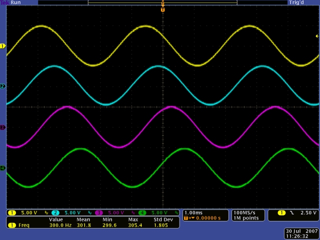
Here's a oscilloscope screen of the four 45 degree outputs when the filter is self-oscillating. This filter is extremely stable. I have verified it against my MOTM-300 VCO and had no discernable drift between the two. The frequency range is very wide compared to other filters.
|
The following are excerpts from various emails I have exchanged with Tim Parkhurst on the filter design and adjustments. Filter
Design
|