|
DJB-008 |
|
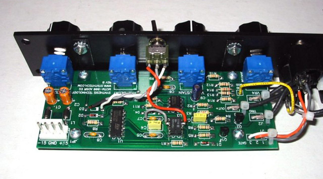
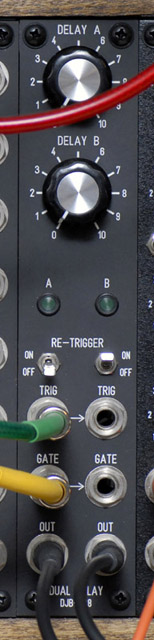
I wanted a couple of DADSR modules so I decided to build a trigger delay. This module outputs a 5 mS trigger pulse that is delayed from the input trigger. Gate false is used to terminate the delay so I start the delay on the falling edge of the trigger input. It can be set to one-shot (will not retrigger until delay is completed) or retrigger (another trigger pulse will restart the delay). The LEDs indicate the delay period.
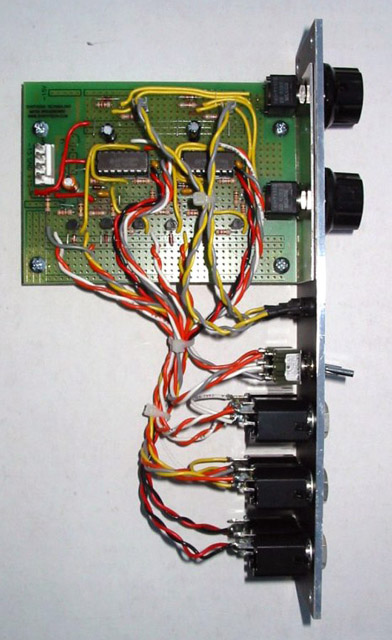
I used a shortened MOTM-000 prototype board to build this module.
DJB-008 FrontPanelExpress design file
MOTM-800 Modifications
One of the issues with a delayed trigger is that this causes the MOTM-800 envelope generator to start in the sustain cycle. I had this same issue with my ARP-3604 keyboard. The MOTM-800 was designed assuming the trigger and gate inputs occur simultaneous. When the MOTM-800 sees a valid gate and no trigger (which also occurs when there no plug is inserted into the gate jack) it begins the decay cycle and remains in the sustain mode. When it sees a valid trigger then it begins the attack cycle but starts from the current sustain level.
This modificaton holds the MOTM-800 off until a valid trigger and then begins the normal ADSR cycle. I added a switch to be able to select either the original or new mode of operation.
The mod consists of adding another CMOS 555 in parallel with the timer on the PCB. Pins 3 and 6 are 'lifted' and the remaining pins (1,2,4,5,7,8) are soldered directly to U2. Pin 6 is the threshold and is soldered to ground. I connected pin 6 to the ground pad on C7. Since there is no threshold voltage, the new 555 will detect the first trigger and remain on until reset by the gate signal going low.
This new output, which is the gate signal held off until trigger, will be used instead of the gate signal at the cathode end of D3 to control the release-sustain cycle. Lift the cathode of D3 and wire it to the center connector on the switch. Wire the bottom connector on the switch to the pad on the PCB where D3 used to connect. Wire the top connector of the switch to pin 3 of the new 555 timer.
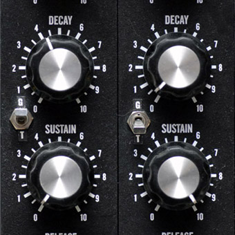
Below you can see the switch I added. The up position is the original mode of operation which is labeled 'G' for gate. The bottom position is the new mode which is labeled 'T' as in wait-for-trigger mode.
Below you can see the simple modification with only a couple of wires added.