|
Moog 907 Fixed Filter Bank |
|
The Moog 907 Fixed Filter Bank has 8 band pass filters and 2 shelf filters (e.g. low pass and high pass). The filters do not have gain but each has an attenuator control. This 907 has switches on each control to disconnect it from the input signal.
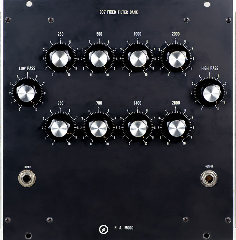
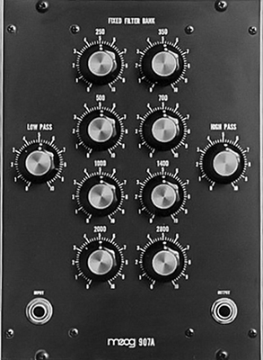
The 907 is a 4MU wide module while the 907-A changed the layout of the controls for a narrower 3MU module.
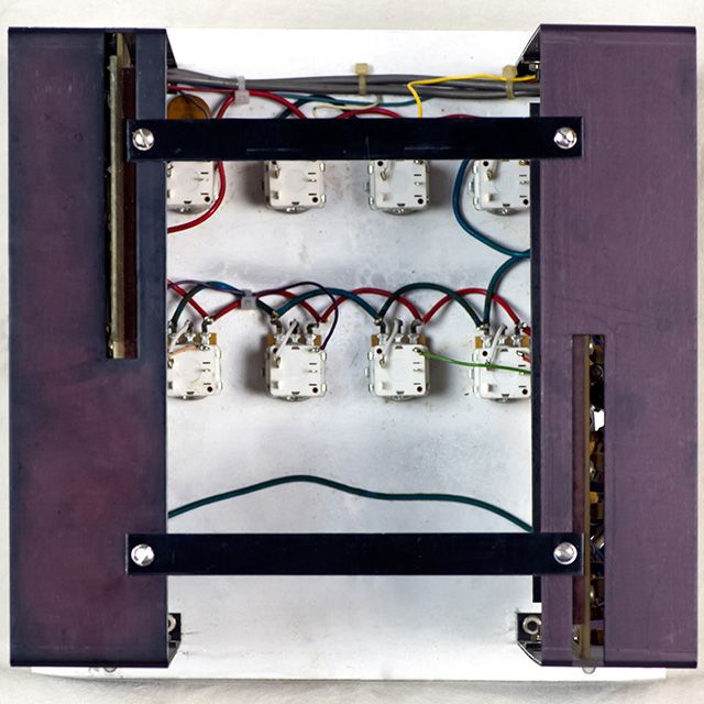
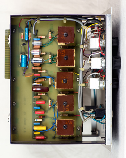
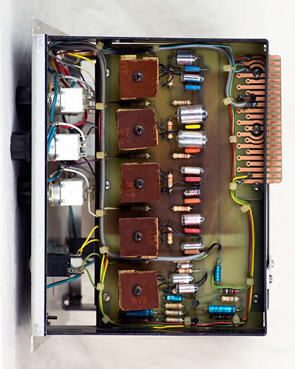
There are two PCBs on each side of the module. The switches were badly corroded and had no continuity. One potentiometer had already been replaced without a switch. The switches were sealed so to clean them required removing the potentiometers, removing the cover, and then removing the switch. I decided they were so corroded to replace the potentiometers. These TE Connectivity (23ESB103MMF50A) 10K log with DPST switch worked great.
Michael Weitman sent me a 360 degree animated GIF of his Model 15 2015 reissue 907A Fixed Filter Bank.
Each PCB has five filter sections.
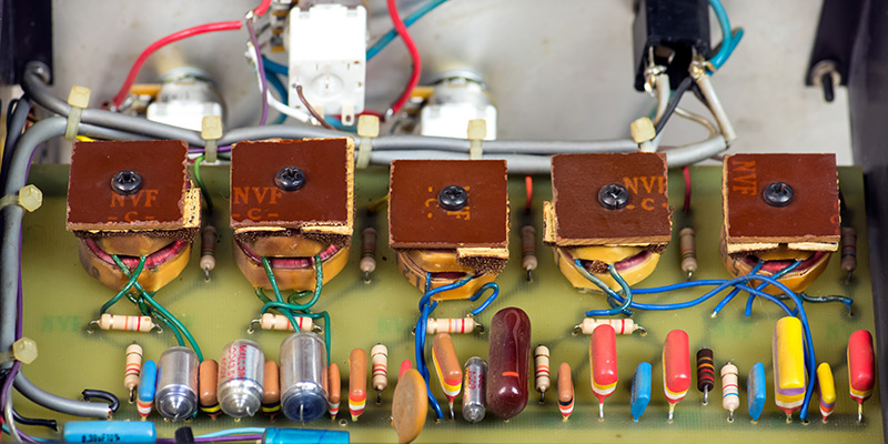
Here is a close-up photo of the coils to see the construction. They are mounted to the PCB with a piece of foam and phenolic on top.
Operation
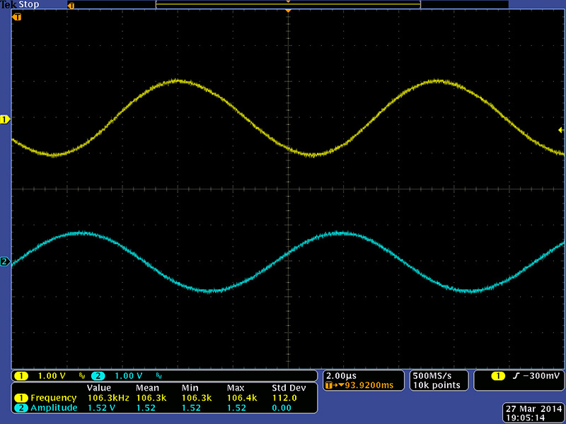
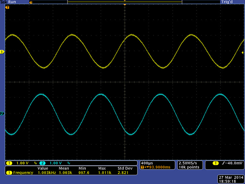
The gain through the fixed filter bank at 1KHz with the 1KHz control at max is -1.35x.
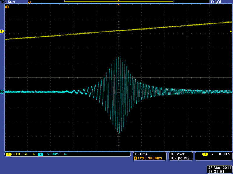
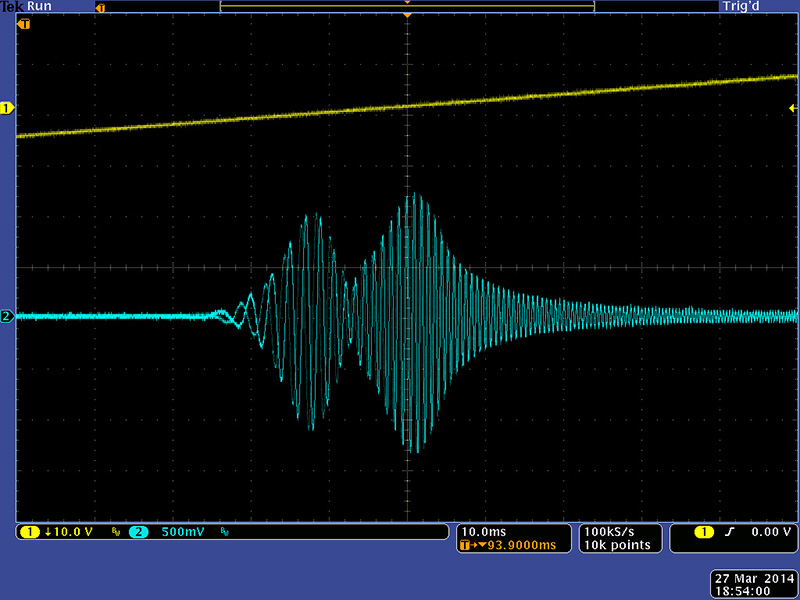
I swept a VCO with a ramp waveform to display the filter envelope. This is the response of just the 1KHz control.
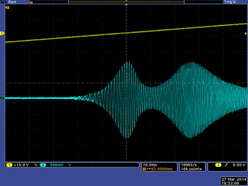
This is the response with the 1KHz and 2KHz controls at max. Each additional filter adds a node in the overall frequency response.
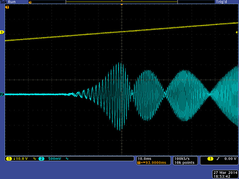
This is the response with the 1KHz, 1.4KHz, 2KHz, and 2.8KHz controls at max. You can see where the 1.4KHz adds a node between the 1KHz and 2KHz nodes.
This is the response with the 500Hz and 1KHz controls at maximum.
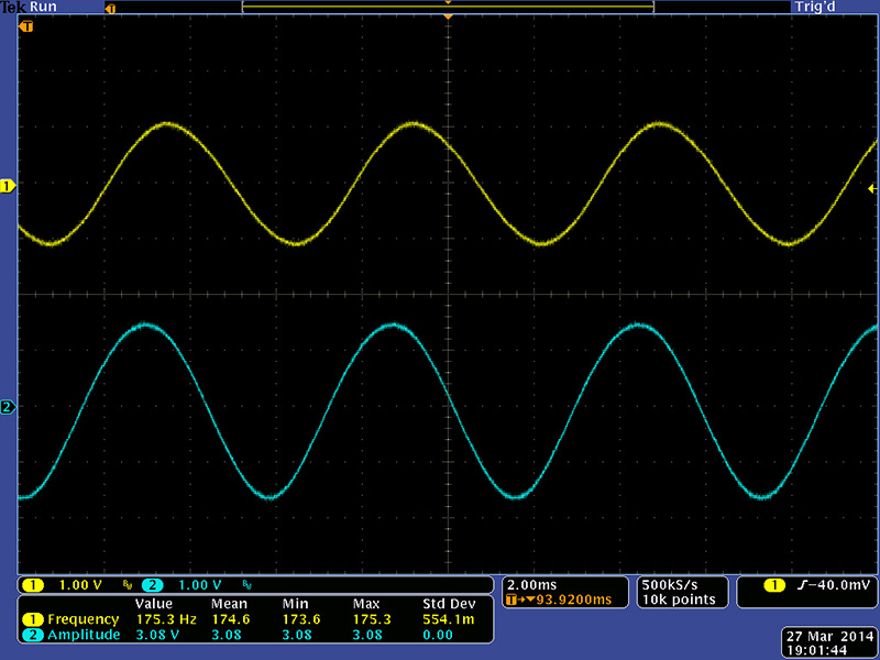
The maximum output voltage for the low pass was at 175Hz.
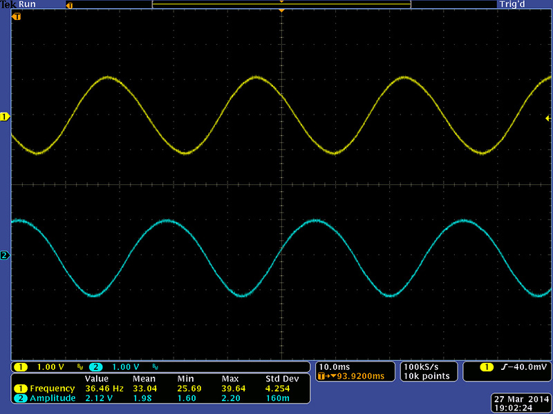
The low -3dB rolloff of the low pass was down to 36 Hz.
The maximum output voltage for the high pass was at 6.6KHz.
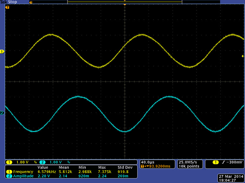
The high -3dB rolloff of the high pass was up over 100KHz so the frequency response of this module is 36Hz - 100KHz.