 |
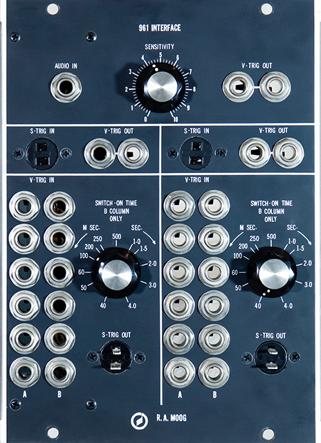
Moog 961 Sequencer Interface |
|
The 961 Sequencer Interface consists of two multi-channel V-Trigger to S-Trigger converters, two S-Trigger to V-Trigger converters, and an audio to V-Trigger converter. A V-Trigger is a voltage trigger which is like a positive voltage Gate pulse. An S-Trigger is an active low "short" to ground signal which can be wired-or'd.
The V-Trigger to S-Trigger consists of six A inputs and six B inputs. The A inputs are level sensitive so the S-Trigger output is the same duration as the V-Trigger inputs. The B inputs are edge sensitive and drive a variable one-shot (using a unijunction transistor) so the S-Trigger output can be varied from 50 mS to 4 seconds.
There is a single PCB in this 3 MU module and is easy to access to all parts. The jacks on this module were in good condition.
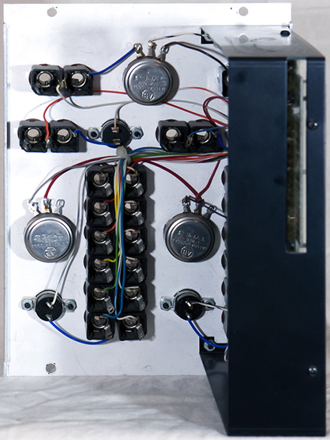
The PCB is mounted on the left with the components facing in.

The PCB solder side faces out. These PCBs are single sided copper with no silk screen or solder mask.
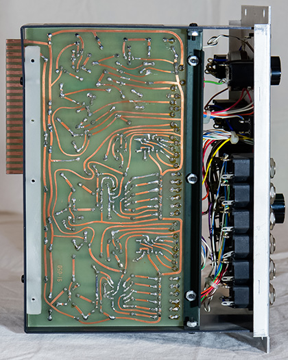
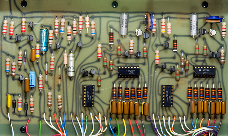
The PCB is single-sided copper with no plating, solder mask, or silk screen. The IC date codes on the RTL are 1969. There is no serial number or date code label on this module.
Operation
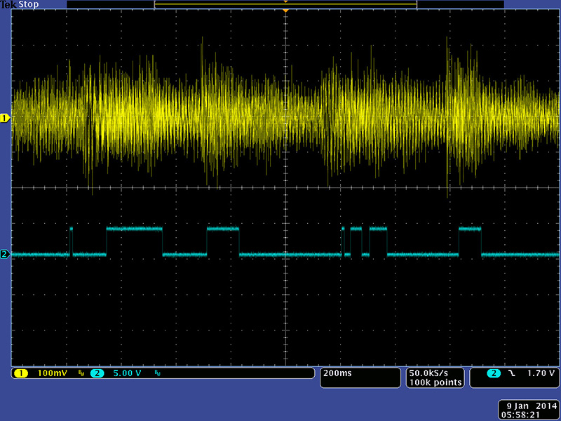
The module has an audio to V-Trig which detects the peaks and can be adjusted with the sensitivity control.
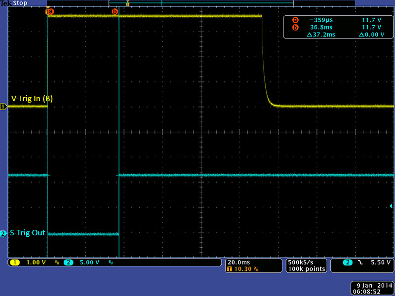
I calibrated the delay to the 500 mS marking at the center of the Switch On Time control. The minimum S-Trig pulse is 37 mS (note that S-Trig is active low).
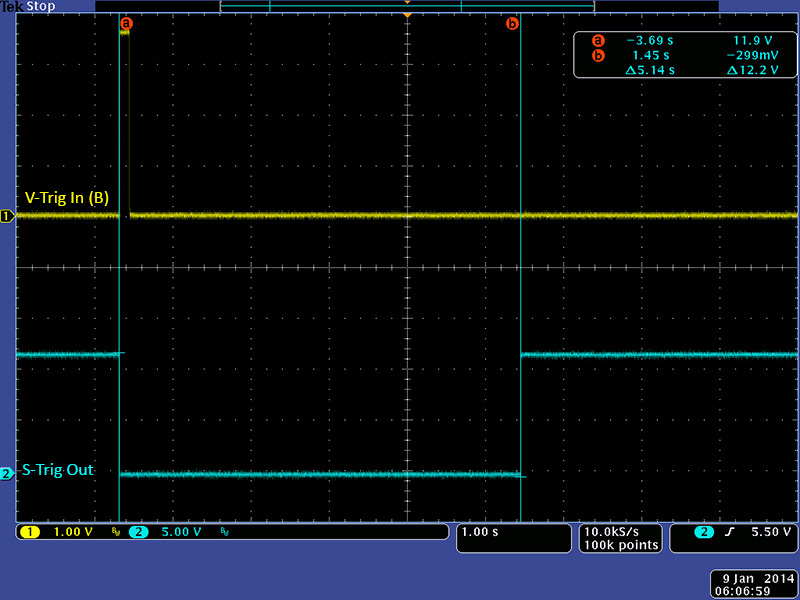
The maximum delay is just over 5 seconds.
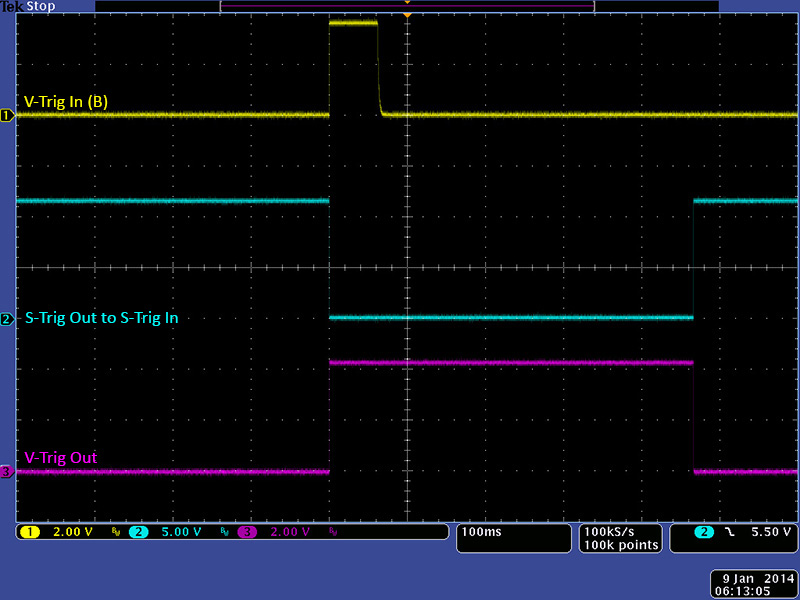
The switch to voltage trigger converts the S-Trig to a 4 volt V-Trig output.
I used the variable V-Trigger to S-Trigger B input to stretch the 960 column 7 Out to 50 mS and ran it through the S-Trigger to V-Trigger converter to connect it to the column 3 In to create a 4 step sequence (columns 3 - 6) as shown in this video.