|
Moog System 55 Internal
Wiring, |
|
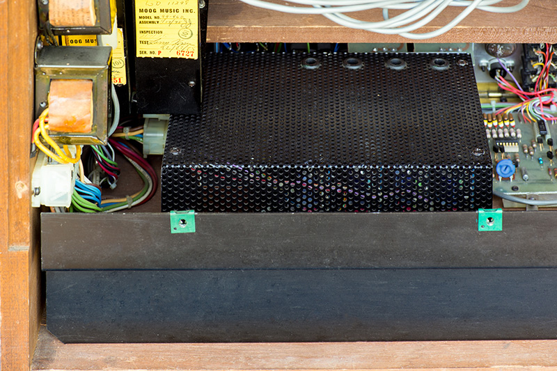
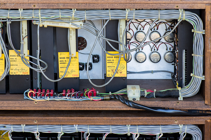
Here are some additional photos of the internals and externals of the cabinets. The two transformers on the left side wall supply the AC power to the incandescent bulbs in the CV and Trigger switches. Below the transformers is the DC distribution strip for half the modules. The 930 power supply is screwed to the bottom of the cabinet and the mains and secondary wiring connects into the side.
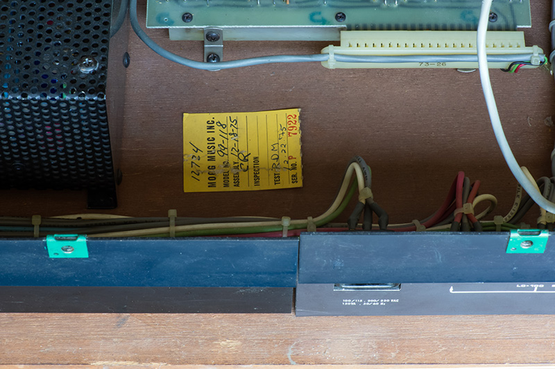
Next to the 930 power supply and directly behind the 961CP main board is a serial number label. I assume this is for the rear panels and internal wiring. I do not know what 99-118 refers to.
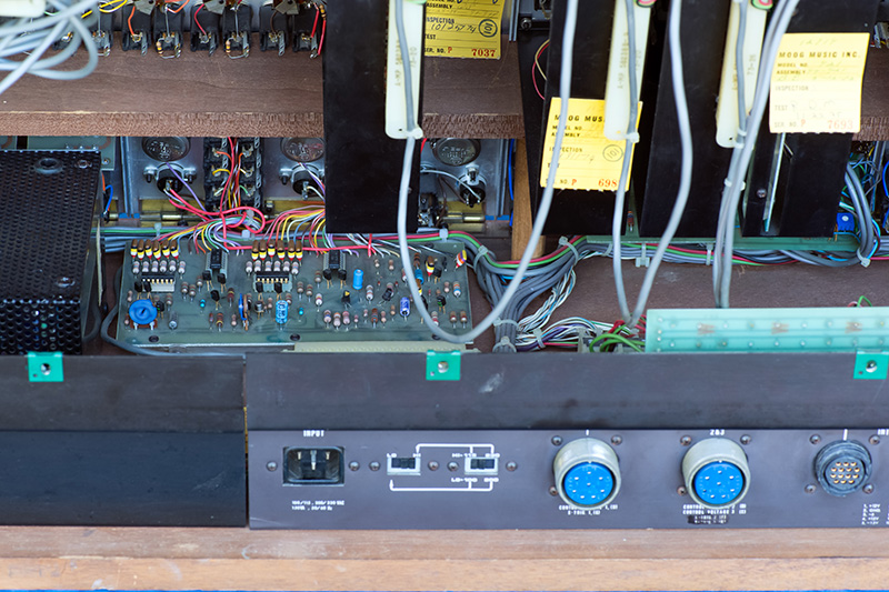
This image shows the 961CP board attached to the inside bottom of the cabinet. The AC mains inlet and line selection switches along with four connectors make up the center of the rear panel.
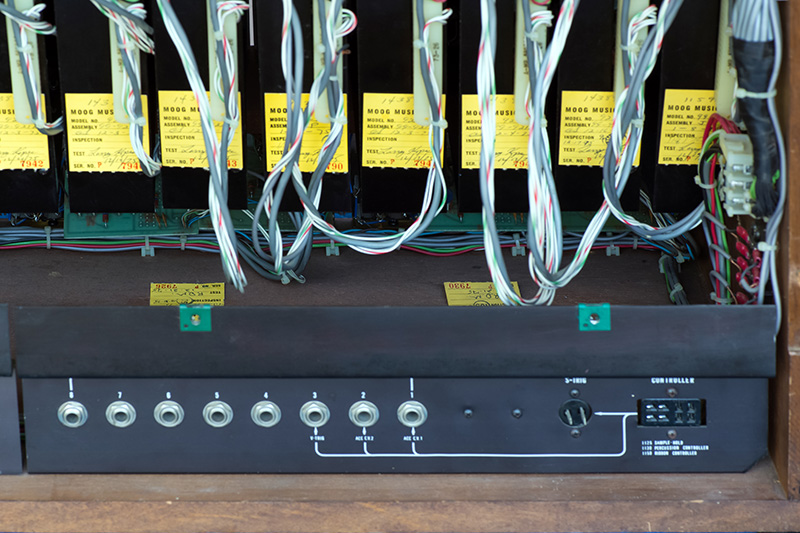
There is a PCB used to distribute the various CV wiring to the console panels and the rear connections. Behind the panel is another distribution strip for power.
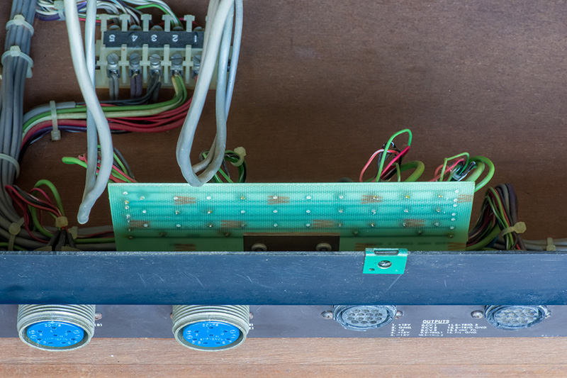
The trunk line jacks and an external controller and trigger jack are on the far right rear panel. On the side you can see the DC distribution strip for half the modules.
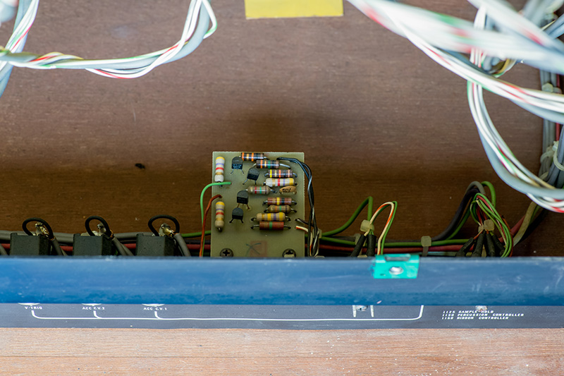
There is a small PCB on this rear panel for the trigger conversion circuitry.
The top cabinet has a straightforward power and signal wiring distribution.
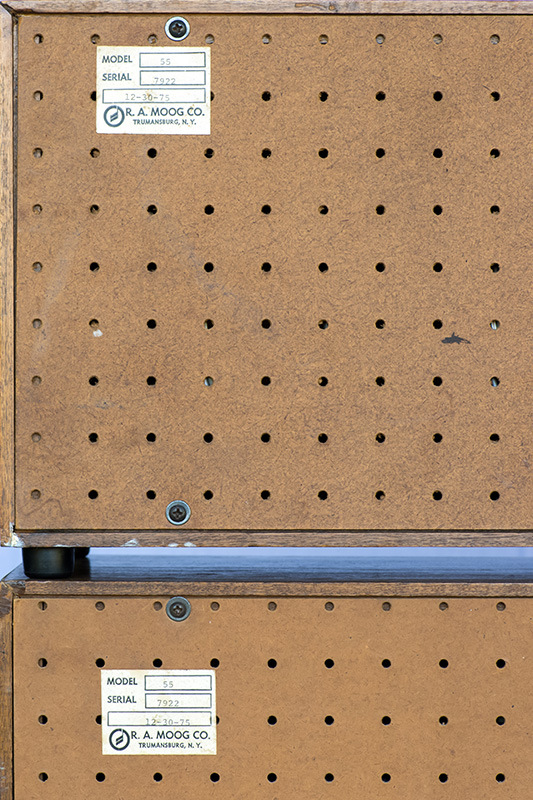
Both rear covers are complete and in good condition.
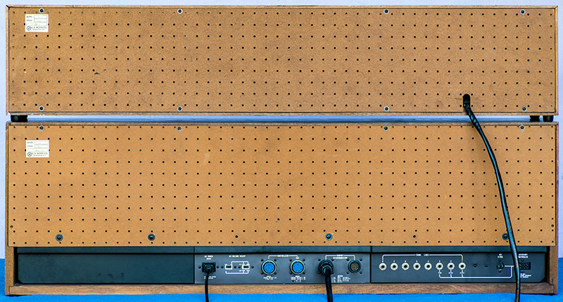
Both cabinets have serial number labels with matching numbers on the rear covers. This System 55 synthesizer was completed on December 30, 1975. Note the label has the old logo.