|
Synthesis Technology 5U E350 Morphing Terrarium |
|
I built the Synthesis Technology E350 Morphing Terrarium kit as discussed in the E350 Morphing Terrarium and the E340/E350 DIY kits forums. This is a 5U format module with additional CV attenuators and all controls, switches, and jacks mounted on the front panel. I also added front panel Smooth (interpolation on/off) and Phase mode switches.
PCB Preparation
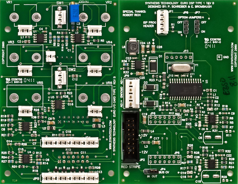
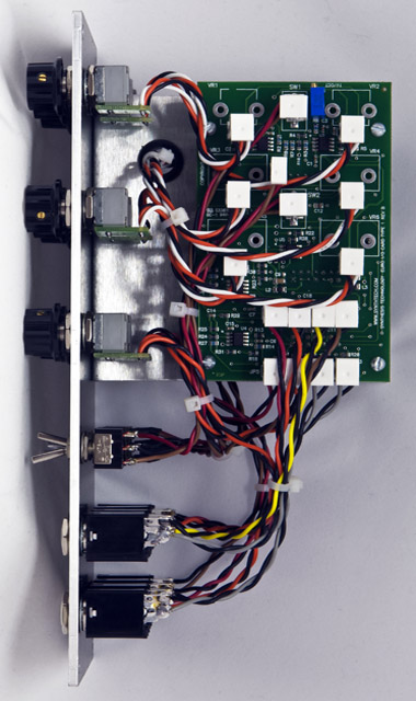
I unsoldered the switches and installed 3 pin MTA connectors for the switches, potentiometers, and in sets of 4 for JP4 and JP5. I had to bend the MTA pins to fit the wider footprint for the switches. Each front panel jack is wired to a separate 3 pin MTA connector.
The Smooth and Phase switches connect to JP6 and JP7 located on the bottom PCB making wiring more difficult. I thought about mounting the two PCBs side-by-side with a reversing cable on the rear so that all panel wiring would be on the top side. JP6 and JP7 ground 3.3 volt logic signals when in the ON position and are wired to JP3 pins 1 and 2. I decided instead to mount the PCBs as designed but added a 2 pin MTA connector on JP3 pins 1 and 2 on the top PCB. The Smooth and Phase switches connect to this new 2 pin MTA connector and the jumpers are removed from JP6 and JP7. The only connector used on the back PCB is the 4 pin power which is accessed through a notch in the bracket.
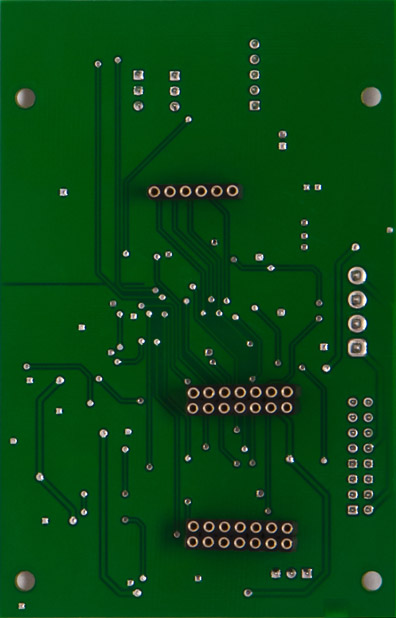
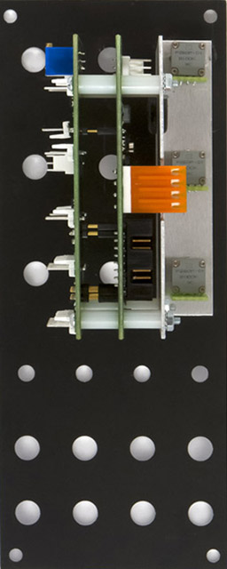
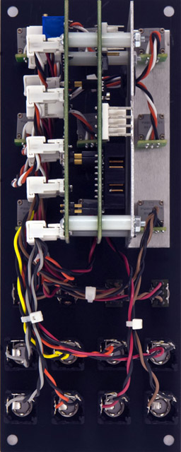
I don't like to solder boards together that cannot be removed for service or future modifications so I added headers to the rear of the bottom PCB. This increased the PCB to PCB spacing to 0.5" which is also the same space between the bracket and the PCB.
The controls and switches wire to the top PCB as follow:
| Control | Function |
| VR1 | Coarse |
| VR2 | Fine |
| VR3 | FM |
| VR4 | Morph X |
| VR5 | Morph Y |
| VR6 | Morph Z |
| SW1 (up) | Range Hi |
| SW1 (down) | Range Low |
| SW2 (up) | Bank A |
| SW2 (down) | Bank C |
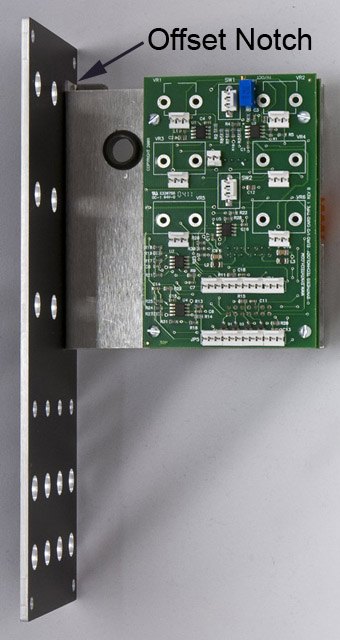
Bracket
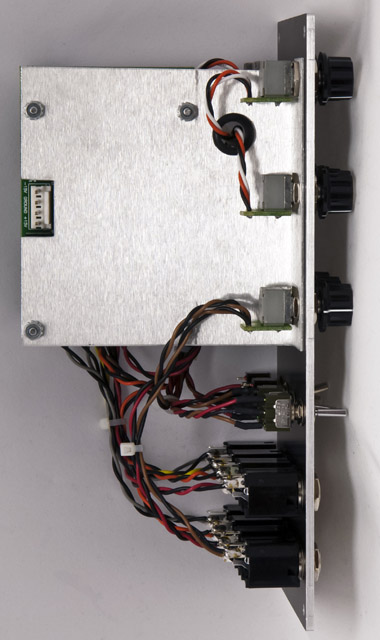
I made a bracket out of 0.050" aluminum 4.75" x 4.125" with an offset notch to increase the PCB clearance to the top of the module to 0.75". I used 0.5" spacers between the PCBs and between the PCB and bracket. The power cable housing extends beyond of the sheet metal bracket which could interfere with the adjacent module. I could have increased the spacer between the PCB and bracket to 0.75" but instead chose to bend the bracket such that the PCB is more centered in the panel. This allows ample room for cables on both sides. I added a grommet in the bracket for the FM and Morph X control wiring.

The offset notch in the bracket increased the PCB clearance to the top of the module to 0.75" while still using the top control for mounting.
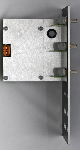
You can see the two pin connector for the Smooth and Phase switches which sits off the PCB and also the power connector that extends through the bracket in this photo. The two color legends on the front panel look very nice.
Wiring
There are a lot of front panel wires on this module. Using a separate 3 pin MTA connector for each control, jack, and switch simplifies the wiring task.
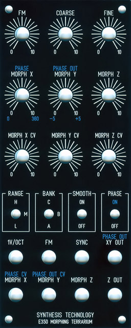
5U Panel Designs
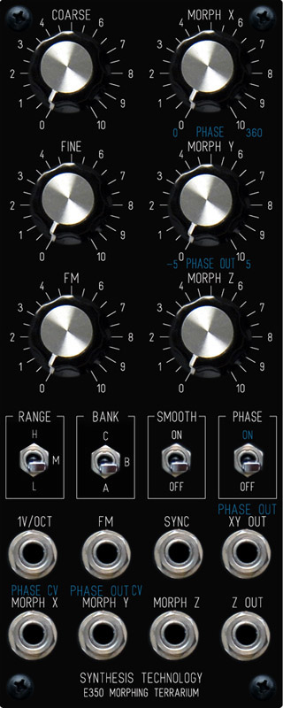
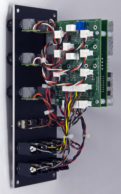
The panel on the left was my initial design using standard MOTM spacing with all switches and controls panel mounted. I added the Smooth and Phase switches with alternate color legends below the controls and above the jacks. Note that I reversed the Bank switch so that up is C.
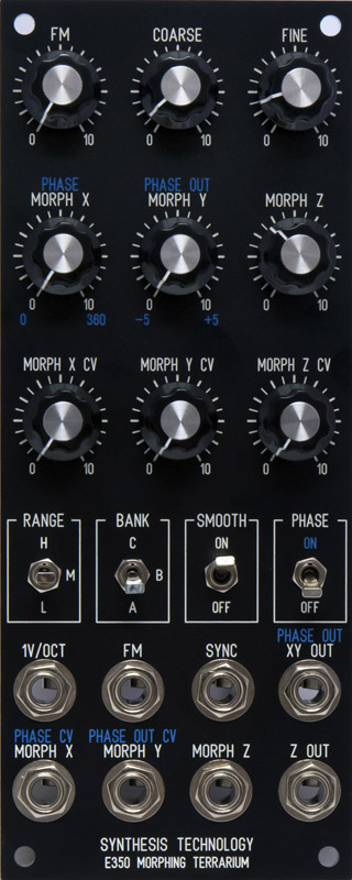
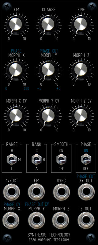
I chose to use the design on the right which incorporates three additional CV attenuators using small knobs on standard MOTM row spacing and the alternate color legends above the controls and jacks. The CV attenuators are a nice feature.
|
|
 |
|
|
DJB-E350 FrontPanelExpress design file (Initial 5U design standard MOTM spacing) |
DJB-E350 FrontPanelExpress design file (Final 5U design with CV attenuators) |