 |
DJB- PSIM Display Project |
|
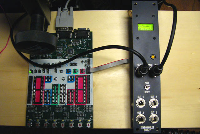
I built a 1U Display module to operate with my PSIM. I used an AVR ATTINY2313 processor to control the display. It operates similar to my external display where the commands operate on an internal memory buffer and the display is refreshed on 25 mS timer interrupts. Here is a photo of my complete PSIM setup with the three modules (PSIM on left, Display in center, and Level Shift on right). The display is showing the MIDI Program Change and Note Velocity information in my CV to MIDI program.

This photo is the display module connected to my AVR development system. I've since replaced the LED with a blue Lumex style indicator.
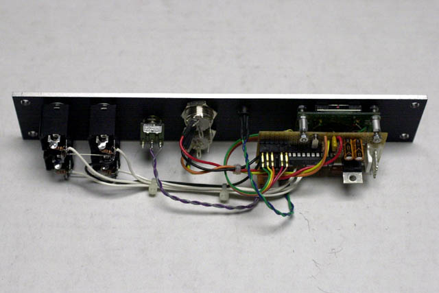
This side view shows the small controller board piggybacked on the LCD display module. The output series resistors are mounted on the output jacks.
PSIM- LCD FrontPanelExpress design file
The display has 192 ROM characters and 8 user-programmable
characters. I default the user-programmable characters to these music symbols:
![]()
treble clef
bass clef
sharp symbol
flat symbol
natural symbol
note symbol
dc (sideways abbreviation for
decimal)
hx (sideways abbreviation for hex)
The software supports the following
display commands:
0x08: move one character back (backspace)
0x09: move one character forward (tab)
0x0a: clear display and set home line1 (line feed)
0x0b: set home line2 (vertical tab)
0x0c: clear display and set home line2 (form feed)
0x0d: set home line1 (carriage return)
0x0e: select character set0
(lower 96 and 8 user-programmable characters)
0x0f: select character set1
(upper 96 characters)
0x10: program
character0 <data1><data2>...<data7> (8 bytes)
0x11: program
character1 <data1><data2>...<data7> (8 bytes)
0x12: program
character2 <data1><data2>...<data7> (8 bytes)
0x13: program
character3 <data1><data2>...<data7> (8 bytes)
0x14: program
character4 <data1><data2>...<data7> (8 bytes)
0x15: program
character5 <data1><data2>...<data7> (8 bytes)
0x16: program
character6 <data1><data2>...<data7> (8 bytes)
0x17: program
character7 <data1><data2>...<data7> (8 bytes)
0x18: select overwrite mode
0x19: select scroll mode
0x1a: reserved
0x1b: reserved
0x1c: set out1 <data>
(2 bytes) where <data> will set, clear, or toggle OUT1
0x1d: set out2 <data>
(2 bytes)
0x1e: set out3 <data>
(2 bytes)
0x1f: set
out4 <data>
(2 bytes)
Here is a close-up photo of the display which shows all four output voltages. I've used the programmable characters to create the sideways O1 - O4 (and also I1 - I4) to indicate the four outputs. In this example, OUT1 is 1.8 volts, OUT2 is 9.9 volts, OUT3 is 2.5 volts and OUT4 is 5.0 volts.

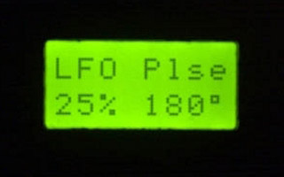
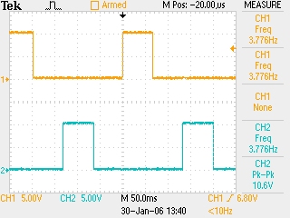
Here is a close-up photo of the display for my Multi Phase LFO program. I display the control settings for the waveform, duty cycle (pulse) and degree offset. A fourth control selects the frequency. Below is a scope image of OUT1 (25% duty cycle) with OUT4 offset by 180 degrees.
Here is a scope image for the same program generating two sine outputs with a 90 degree offset.
