 |
Elks 11th Hour Clock |
|
I was asked to see if I could repair this 11th hour clock for a local Elks Lodge. The hour of 11 has a tender significance. All Elks Lodges will toll 11 strokes with a toast to remember all departed Elks. This one was made in the late 1970s by the 11th Hour Manufacturing Company in Illinois.
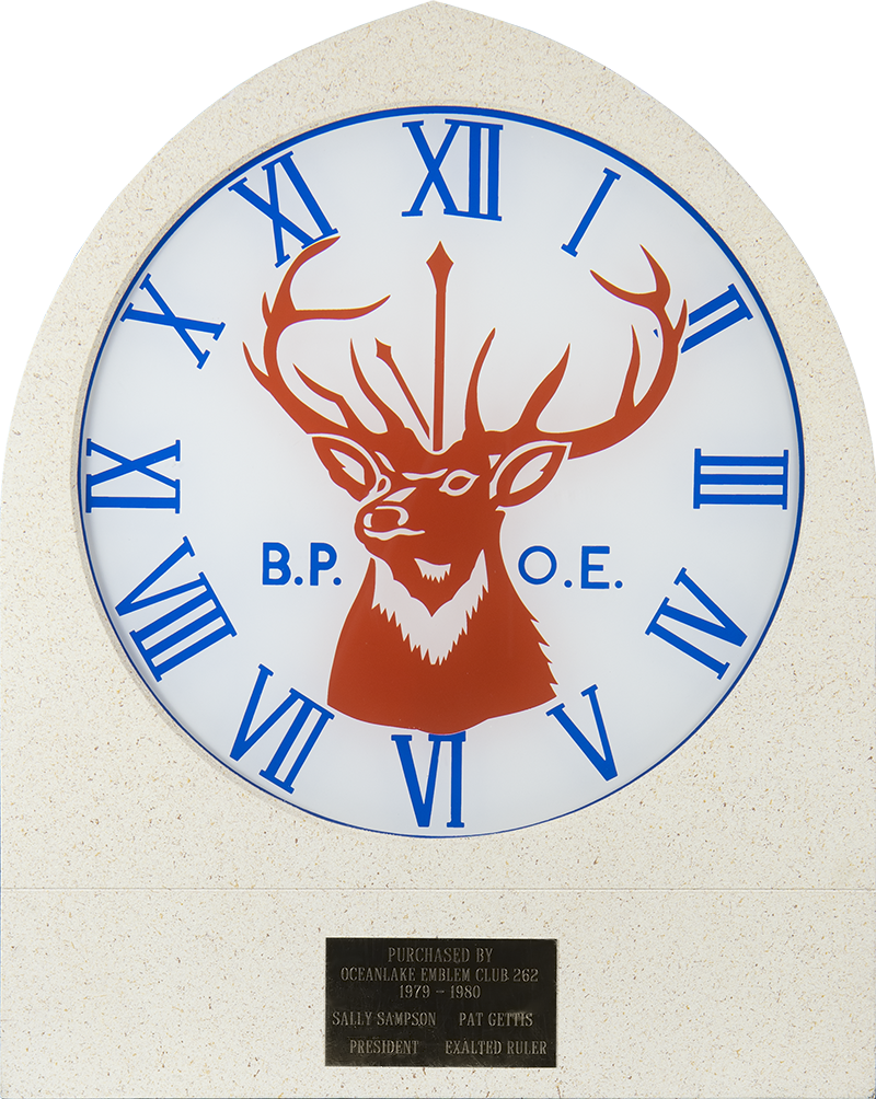
It was a simple design with TTL circuitry and utilized a doorbell for the chime and 7.5W 120V lamps to light up the entire face. It supposedly would only chime once but was completely dead when I received it. The circuitry inside was as line mains potential due to the SCR switch for the lights. The power supply tantalum capacitor was shorted so I replaced it. However, it was still dead. All of the nomenclature on the ICs and 3 terminal regulator was sanded off supposedly to protect the design. Well, it also prevented any service. I surmised the regulator was a 7805 based on the voltage of the tantalum and replacing it brought back just the single chime. It would have been a lot of work to reverse engineer and figure out what all the ICs were. I decided it would be better to just redesign it.
I thought that the entire clock could run on 5V with LED lighting, a microprocessor for control, and a mp3/wave player/speaker for the chimes. I wanted each of the numerals to light up with the chimes so decided on 11 hour LEDs and a center LED. I needed a couple of control lines for the mp3/wave player and an input switch. I chose an ATTINY2313 as it had the right number of IO pins.
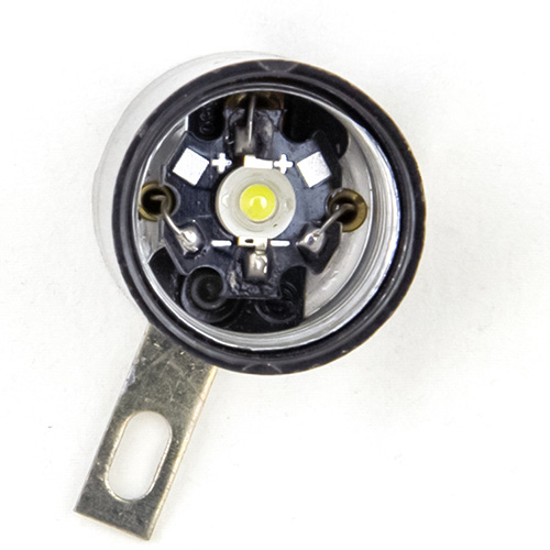
My first effort was to determine how to illuminate the hours. The face was fairly opaque so I chose 1W LEDs. I needed to collimate them so they would only light up the individual hour numeral and chose to mount them inside the 120V AC sockets. I used three solid wires to solder to the three eyelets. The collimation works quite well for the hour digits.
I only program in assembly so wrote a quick program to control the 12 LEDs and sounds. An external 5V 2A regulated supply was used so inside the clock is only low voltage.
I have two versions. One only runs once and then halts which prevents a false trigger if it is left powered on. The other runs, waits 5 seconds, and then restarts waiting for a start for clocks that the power is wired directly.
I used a DF Mini Player module for the Oscilloscope Music exhibit at the vintageTEK museum and it worked well, so I used one for the audio. It will directly drive a speaker with sufficient volume and has two hardware trigger inputs to play different mp3/ wave files. I used a gong sound for the hours and Big Ben chimes at the very end. These inputs were designed for switches to ground, so I used transistor drivers. The sound files are on a micro-SD card and the gong/hour needs to be file 001 and Big Ben/ending file 005. I replicate file 001 as file 002 - 004. You can substitute any sound files on the micro-SD card or edit the default files to change the volume. The duration of the files need to be less than 5 seconds to coordinate with the lights and timing.
Feel free to use this design and files.
11th Hour Clock ATTINY2313 hex file (run once) Fuse Bits: Ext=0xFF High=0xDF, Low=0xE4 Int RC Osc. 8 MHz startup long
Construction
I found that about 250 mA worked well for the hour LEDs and 180 mA worked well for the center LED. I used transistor drivers for each of the LEDs. In this build I chose separate resistors for each of the hour LEDs since I thought I might have to modify some. The lighting was uniform, and since only one hour is on at a time, I could have wired all the LED anodes together with a single series resistor. With the 1W LEDs I used, 5R7 0.5W worked well for the hour digits but were expensive, so I used two paralleled 11R5 1/4W resistors. A 13R 1/2W resistor worked well for the center LED.
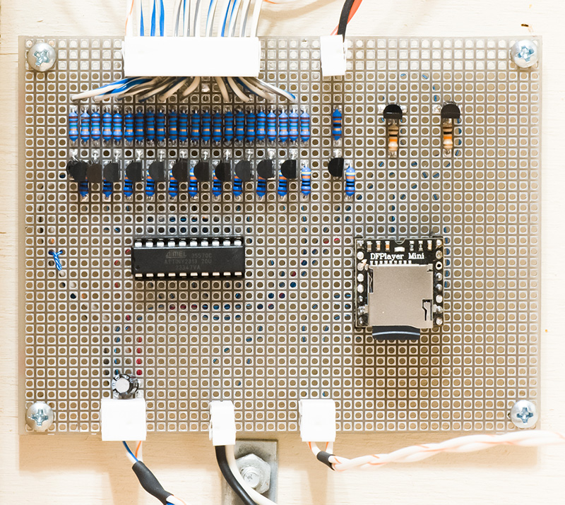
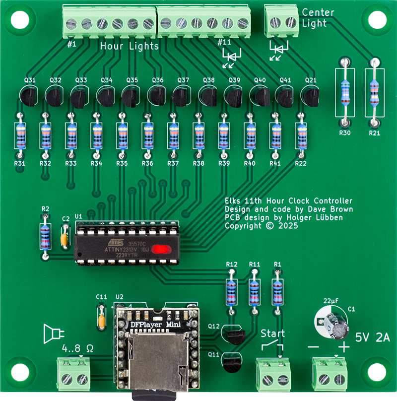
I didn't take the time to lay out a PCB but hand wired it. The top connectors are the hours and center LEDs. The bottom connectors are power, trigger switch, and speaker. You can see the micro-SD card plugged into the DF Mini Player module. You can also see all of the individual hour LED resistors.
The inside wiring is pretty simple. I mounted an 8" speaker to the rear in the cutout for the doorbell. The power supply is external to the clock.
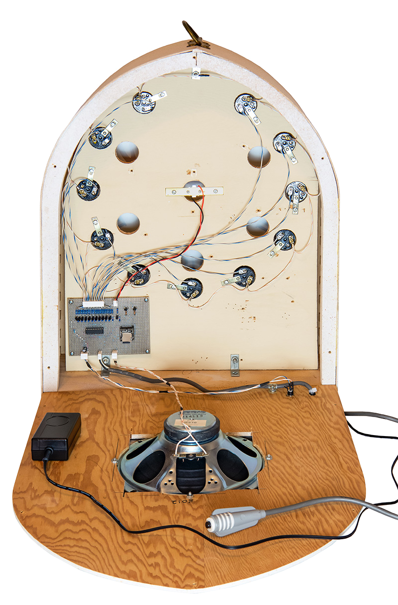
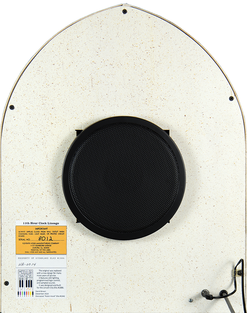
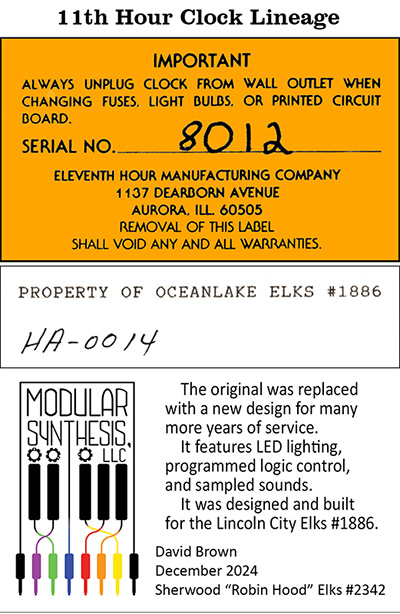
I added a label to show the lineage of this clock over the past 45+ years.
Here's a video of the clock in operation.
Epilog
I've had a number of Lodges ask for help with their broken 11th hour clocks. I had a PCB designed which makes this project more possible. Due to the size, weight, and fragile nature of the clocks they really need to be rebuilt locally. This PCB is designed so there is no soldering with all connections made by screw terminals. The rebuild would consist of replacing the chimes/doorbell with a speaker and grill, soldering and mounting the LEDs, and wiring it all up. I might be able to help with LED soldering depending on the clock. Contact me for details.
This isn't a regular stocked item as I am doing this to help. I can order parts and assemble the boards, and program the parts as needed, assuming the demand stays reasonable. Price for an assembled and programmed card with power supply is $120 + shipping.
I've worked with a number of Lodges to help in rebuilding their 11th hour clocks. Some are larger wall clocks which had a need to drive more than a single LED for illuminating various sections. The sink transistors and this board were not designed for multiple LEDs. I sketched up a PNP circuit using a TIP32 transistor that can drive multiple 1W LEDs (see Sherwood, OR #2342 below for details).
The LEDs I used for this project are no longer available but a number of similar types are available on Amazon in quantity.
280-350mA 1W LED Chip Bulb COB Light Beads
Pure White Super Bright High Power for Floodlight
6000-6500K
Lodge Clock Rebuilds