|
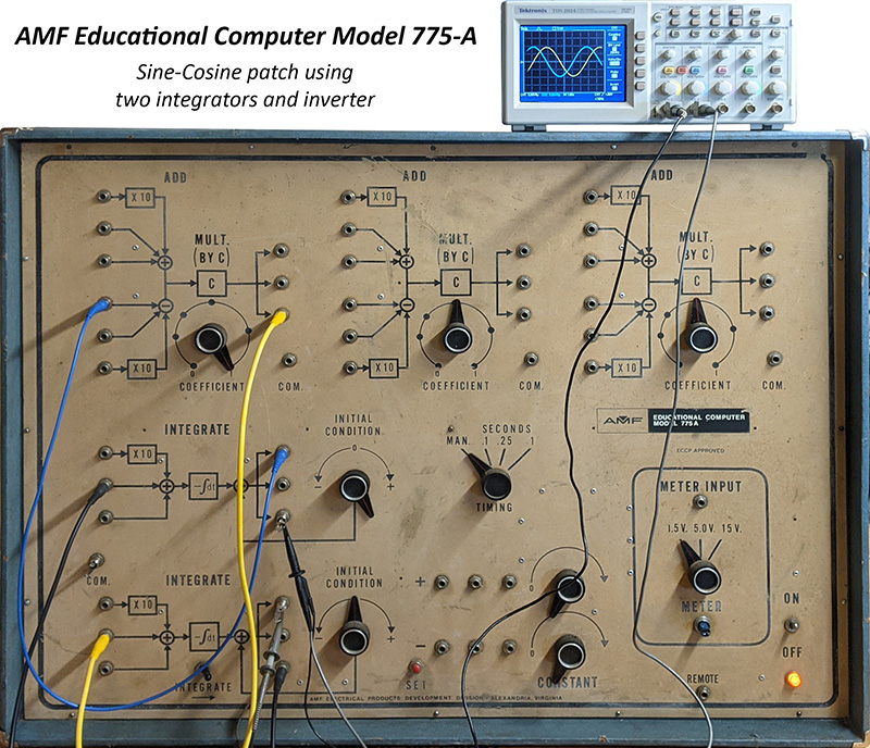
AMF Educational (Analog) Computer Model 775-A |
|
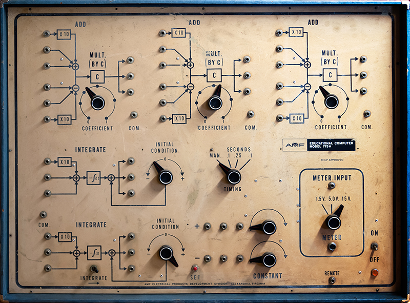
There is nearly no information on this analog computer trainer. It is pretty basic with limited functions. The panel is wood and the front surface is a bit oxidized. The controls took a bit to figure out and there is literally no information on the web.
I traced out the integrator and timer PCBs to understand their functions and calibrate them.
Integrator and Timer schematic
¤ The Set button initializes the integrators to the Initial Condition value.
¤ The Integrator functions only when the Integrate switch is activated (to the right).
¤ When activated the integrator functions for the duration set by the Time Switch with Man being continuous.
¤ I believe grounding the Remote jack simply activates the integrator in Man mode.
¤ The Meter Output jack is a strange configuration. I made a pin plug to fit.
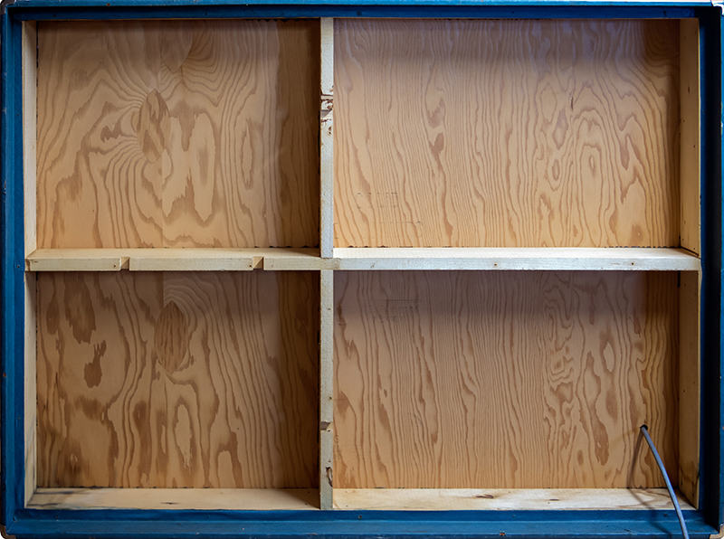
The circuitry is pretty basic. Everything is riveted together. What's interesting is the ground lugs of the open frame 1/4 phone jacks are not wired, but a separate 1/4" phone jack provides the 0V reference.
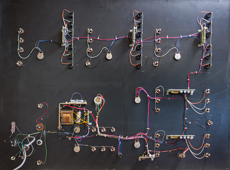
The cabinet frame has routing to accommodate the wiring.
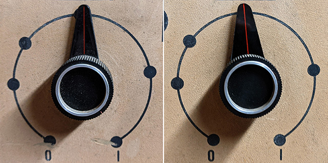
Two of the pointers were broken off so I made new ones from 3/32" Plexiglas. The original is on the left and my reproduction is on the right.
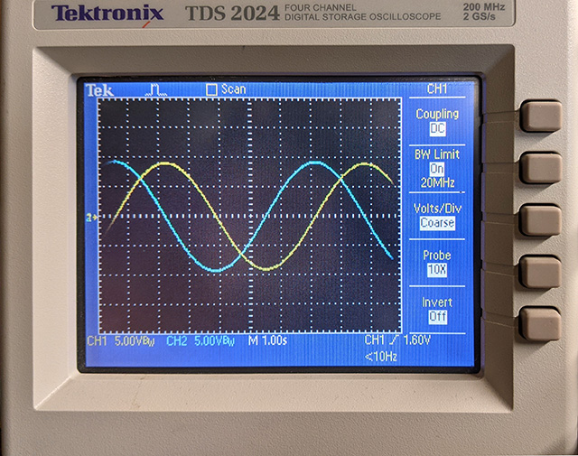
Here is a simple patch generating a sine and cosine wave. The integrator time constant is fixed so the frequency is pretty slow.