|
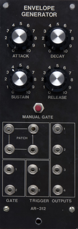
Aries
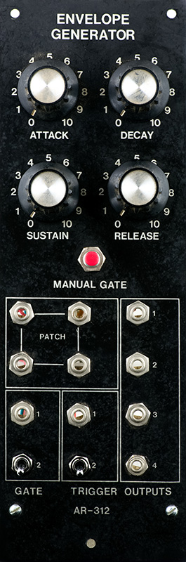
AR-312 |
|
Aries modules were available both as kits and factory modules. This module sold in 1975 for $49.50 in kit or $99.00 assembled and raised slightly in 1977 to $61.00 in kit or $110.00 assembled. This module appear to be a kit due to the build and solder quality.
I combined specifications and schematics from Robert Leiner (with permission) and my photos into a PDF document. Note that R31 has been corrected in the schematics connecting to -15V instead of ground.
AR-312 Envelope Generator Document
Aries AR-312 Documentation (compliments of Michael Gilbert)
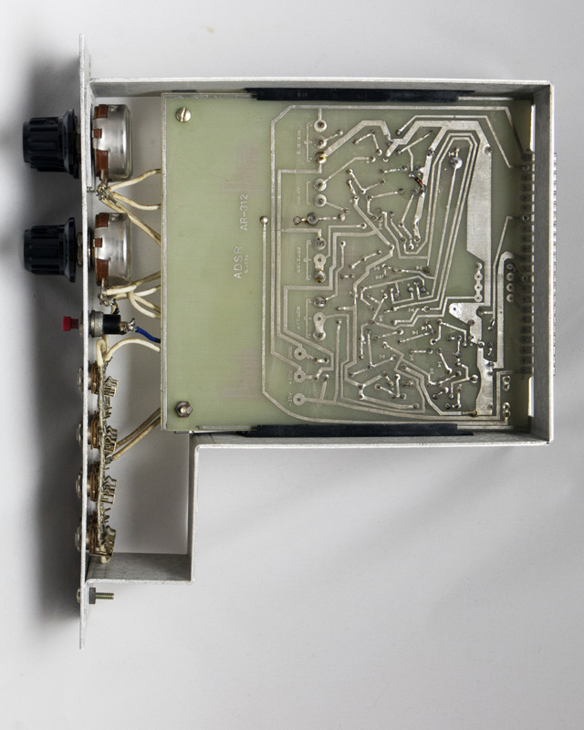
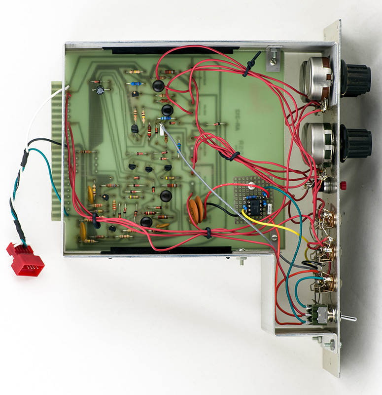
I have not been able to find PCB layout information but this is a pretty simple design and both sides of the PCB are easily accessible.
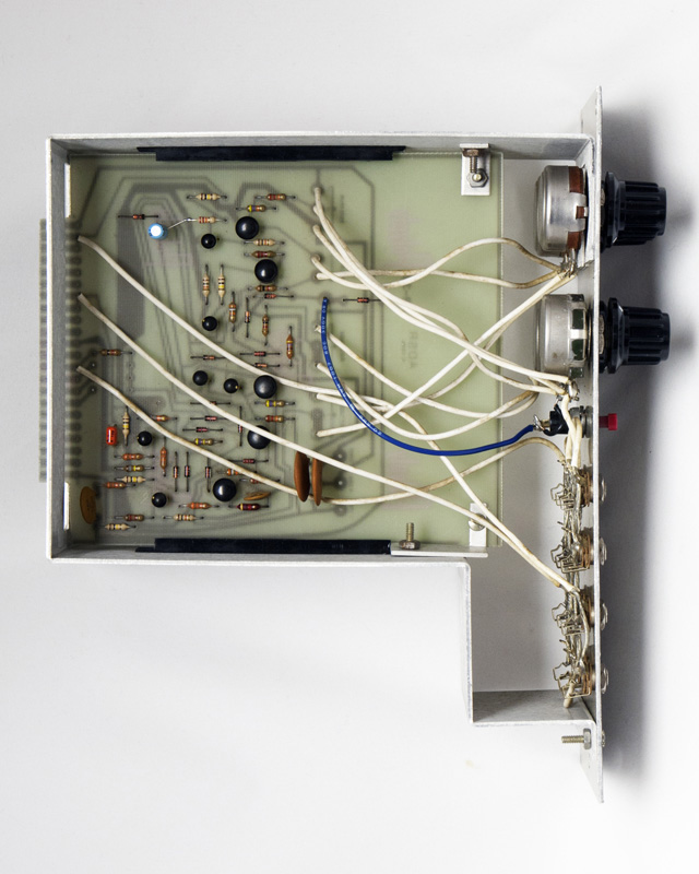
The PCB is a single sided tin with no solder mask. Care is required when doing repairs as the pads do lift easily.
The AR-312 EG operates with 10V trigger and gate inputs but I modified the circuit to operate with 5V inputs by changing R4 to 20K and C4 to 0.1 µF.
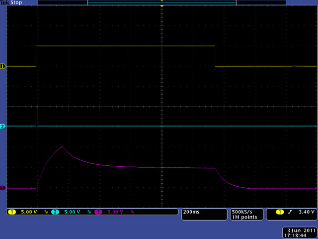
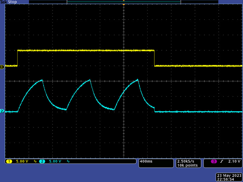
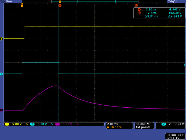
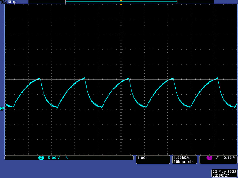
This scope image shows the minimum attack and release times. Note that the release cycle does not start until the trailing edge of trigger as shown by the flatted portion between attack and release.
The measured minimum and maximum delay times for each phase is:
| Minimum Time | Maximum Time | |||
| Measured | Specified | Measured | Specified | |
| Attack | 3.5 mS | 2 mS | 5.8 Sec | 4 Sec |
| Decay | 8.8 mS | 2 mS | 8.8 Sec | 2 Sec |
| Release | 5.0 mS | 2 mS | 6.0 Sec | 2 Sec |
Epilog
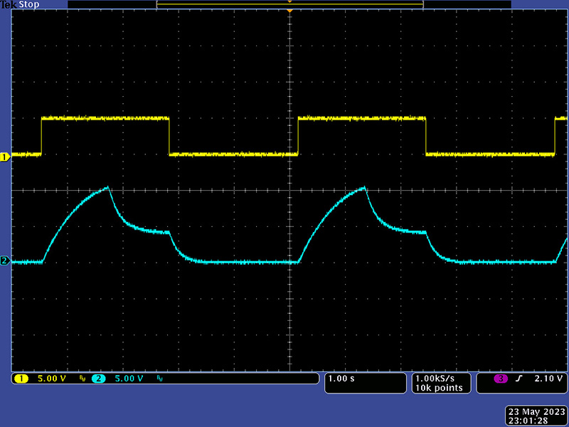
I was asked to modify an AR-312. The first modification was to lower the trigger level so a 5V Gate would work. The second modification was to make it operate with a Gate only. This scope image shows a 5V Gate normal ADSR operation.
The third modification was to add a looping function. The issue with this design is it has two Gate inputs and two Trigger inputs which are simply paralleled. That means if you plug two Gates or two Triggers they simply fight each other. This module can only be used with one Trigger and Gate input and the second jacks are really just outputs which eliminates the need for a Mult. I repurposed the bottom jacks with switches to control the various modes as shown in this table.
| Gate Switch (left) | Trig Switch (right) | Gate Jack | Trig Jack | Output/Function | Comments |
| Down | Down | Gate | Optional | Normal AR-312 ADSR operation | Gate is normalled to trigger so trigger is optional |
| Down | Up | Gate | NA | Gated mode; AR Loops when Gate is true | Sustain and Release set to full CCW |
| Down | Up | NA | Trig | No output | No Gate input to start or sustain loop function |
| Up | Down | Gate | NA | Initial AR cycle to continuous Sustain | Gate is always true when left switch is up |
| Up | Down | NA | Trig | Initial AR cycle to Sustain with retriggered AR cycles | Gate is always true when left switch is up |
| Up | Up | NA | NA | AR loop mode | Gate switch must be turned on second to trigger initial cycle; Sustain and Release set to full CCW |
| Up | Up | NA | Trig | Initial AR cycle to Sustain with retriggered AR cycles | Sustain and Release set to full CCW |
The bottom two jacks have been replaced with switches.
You can see the small comparator PCB in this photo.
Operation
This scope image shows a normal loop mode. The EG circuit has some instabilities which I could only eliminate by increasing the minimum Attack and Release times slightly.
This scope image shows a gated loop mode.