|
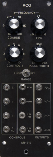
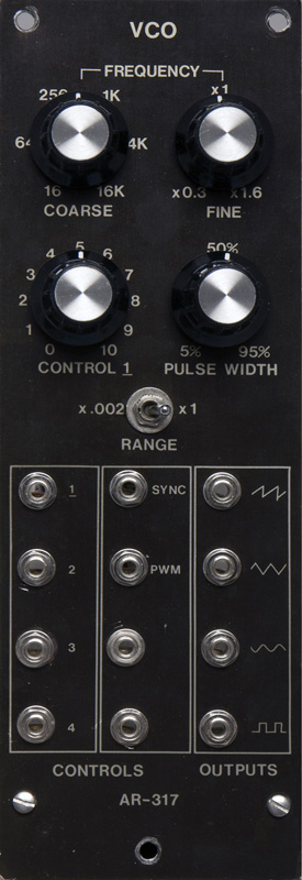
Aries
AR-317 |
|
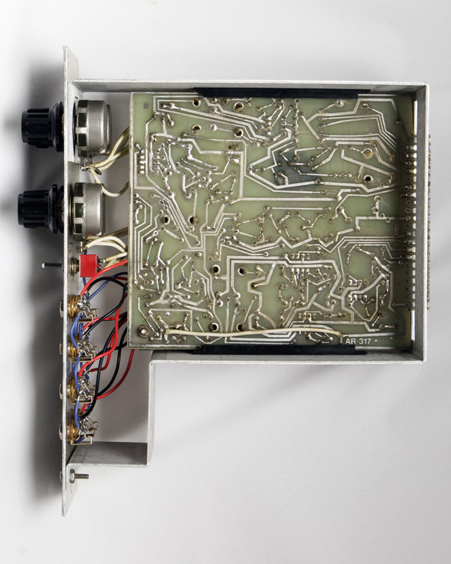
Aries modules were available both as kits and factory modules. This module sold in 1975 for $69.50 in kit or $139.00 assembled and raised significantly in 1977 to $125.00 in kit and $182.00 assembled. This module appear to be a kit due to the non-uniformity of components and wires as well as the build and solder quality.
I combined specifications and schematics from Robert Leiner (with permission) and my photos into a PDF document. I've updated the schematics by correcting R14 and adding the value for R71.
Aries AR-317 Documentation (compliments of Michael Gilbert)
I have not been able to find PCB layout information. Some components are placed somewhat randomly on the PCB so tracing the circuit takes time. Access to portions of the PCB component side is also challenging due to the bundle of front panel wires.
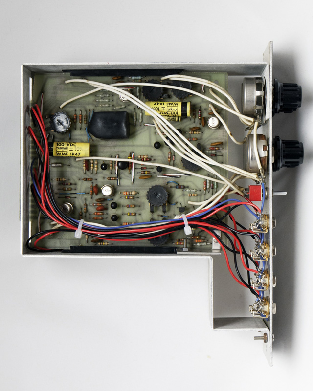
The PCB is a single sided tin with no solder mask. Care is required when doing repairs as the pads do lift easily.
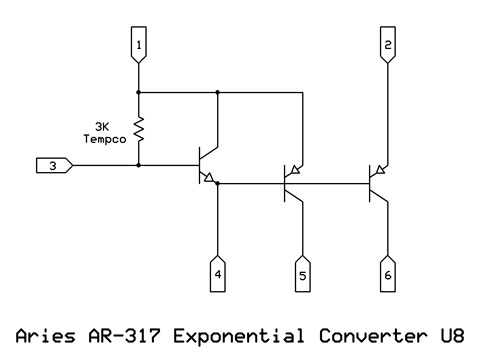
Exponential Converter U8
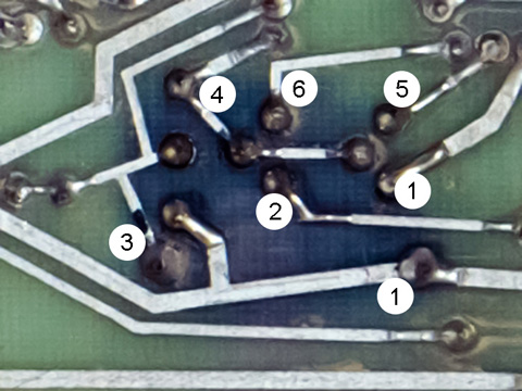
Here is a close-up image of the rear of the potted exponential converter U8. I had assumed this potted module would only have 6 pins corresponding to the schematic but you can clearly see the layout for three transistors and the tempco resistor across the bottom. I have added the pin designations corresponding to the schematic. One can trace out the schematic as shown below.
This is the schematic of the AR-317 potted exponential converter U8.
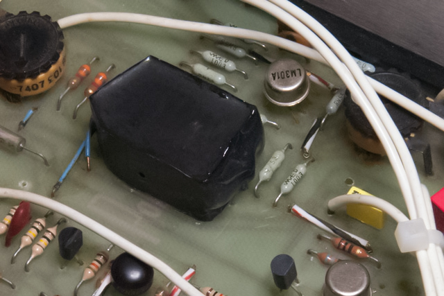
The NPN transistor in the exponential converter module U8 was dead. I tried to remove the exponential converter module but the module is apparently potted on the PCB. Since there was no way to remove the module I thought about building a new module and mounting it to the back of the PCB. Since only the NPN transistor was bad, I decided to mount a new transistor next to the module. This placement allowed the transistor leads to simply be bent and soldered to the correct traces.
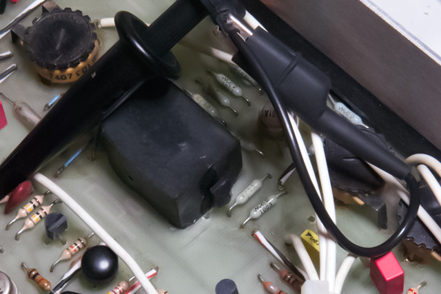
I attached the NPN transistor with epoxy to the exponential converter module U8 for good thermal conductivity.
Adjustments
There are six different trimmers requiring adjustment which I've identified in this photo.
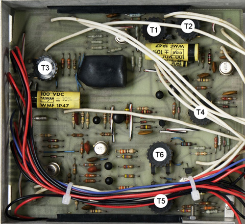
| Trimmer | Adjustment |
| T1 | 1V/Octave |
| T2 | Initial Frequency |
| T3 | Sawtooth Amplitude |
| T4 | Sawtooth Offset |
| T5 | Sine Purity |
| T6 | Sine Symmetry |
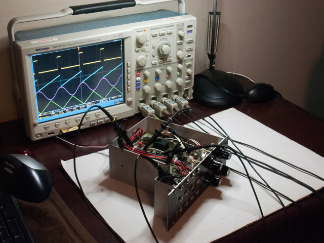
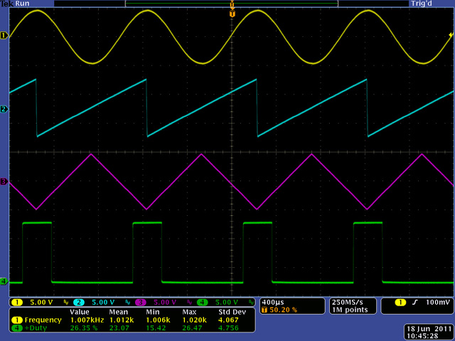
This scope image shows the four simultaneous outputs. They are all very nice waveforms.
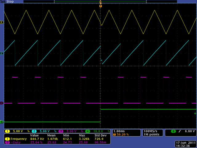
This scope image shows the VCO sync to an external square wave (green).
Modifications
The build notes suggest adding linear FM by connecting a 330k resistor from an unused jack to pin 4 of the exponential converter U8. Positive voltages decrease frequency and this affects the 1 Volt/Oct calibration. You can AC couple this input with a 0.1 µF capacitor to eliminate the DC detuning affect.
There are two unused jacks on the front. One is a bit off-grid so I think perhaps the user would drill and install these as needed. Options for these unused jacks include an AC FM input, a linear FM input, or an AC linear FM input. There is even room to add small 1/8" potentiometers instead of jacks to provide level controls for inputs 3 and 4.
I modified this AR-317 by changing FM 4 to AC coupling, adding a linear FM input, and an AC coupled linear FM input.