 |
102 Stereo Locator Clone Module |
|
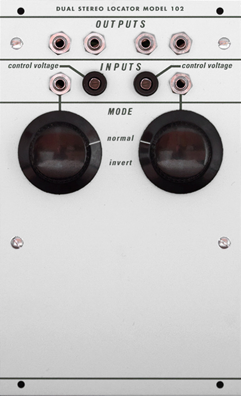
Someone sent me their home made 102 Stereo Locator module that didn't operate properly. This is a fairly simple module using JFETs as variable input resistors to cross fade inputs between two channels. These must be rare as there are few photos. This photo is from www.theonehundreds.com/.

The output op-amp is biased up at 15 using a 24V supply. The JFETs are also biased up at 15V. The design calls out 5% resistors but this results in the op-amps being biased several hundred mV apart. I changed several resistors to 1% and this brought the bias point of the op-amps nearly equal.
I could not get the circuit to operate properly per the schematics. When one channel is normal and the other invert, the input is mapped to both outputs and the op-amp inputs are connected in parallel. This changed the DC operating point and the output signals became quite distorted.
I was looking for a simple way to maintain the DC operating point the same whether the inputs were connected together or not and simply AC coupled them using a 1 µF capacitor. This worked fine for holding the DC operating point but the amplitude dropped to half when the input was mapped to both outputs.
Instead I added a 15K input resistor to isolate the two op-amps when connected together and increased the feedback resistor to compensate. Now the module works as intended.
102 Stereo Locator schematic modifications