 |
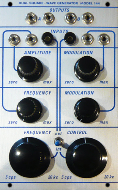
144 Dual Square Wave Generator Module |
|
I helped an individual by email to debug their 144 Dual Square Wave module by sending him this brief circuit description.
Circuit Description
The module is a unipolar ramp core VCO followed by a discrete multivibrator that is triggered by the ramp reset pulse and divides by two. The amplitude of the resulting unipolar square wave is adjusted by a variable clamp circuit. The output is an emitter follower that is AC coupled to produce a bipolar square wave signal using only +15V supply.
C3 is the timing capacitor. It is reset high and charges low. Q6 is a JFET to buffer the ramp with a high impedance. load. R18 sets the amplitude and R21 feeds the buffered ramp waveform to the base of Q5 which then resets the ramp when the base voltage is 0.6V less than the trim voltage. This turns on Q4 and Q3 to reset the ramp.
Q4 also sends the reset pulse via C6 to trigger a divide by two multivibrator consisting of the Q8 and Q9. The ramp level is somewhat unimportant since the reset is used to trigger the multivibrator. However, the ramp level impacts the frequency range. R4 and R9 set the frequency range and lowest frequency.
The collector of Q9 is the output of the multivibrator. Q11 sets an upper and lower clamp voltage via CR4 and CR5. R36 adjusts the collector and emitter voltages and sets the overall amplitude of the square wave. AM modulation is AC coupled and modulates the emitter and collector voltages of Q11.
When the square wave at the collector of Q9 is high, the output is attenuated by R46 and R41 to the high clamp voltage of CR4. CR5 is reversed biased. When the square wave at the collector of Q9 is low, Q10 is turned off so its collector goes high and the output is attenuated via via R33 and R34 to the lower clamp voltage of CR5. CR4 is reversed biased.
This amplitude controlled square wave is buffered by Q12 as an emitter follower and then AC coupled with a slight attenuation by R43 and R44