|
Buchla 208 Stored Program Sound Source |
|
I received an original Music Easel to calibrate and repair. From the date codes on the ICs it looks like this was made after the 39th week of 1973 so either late 1973 or early 1974.
|
A scan of the manual |
|
|
A better color scan of the manual contributed by Luther R. |
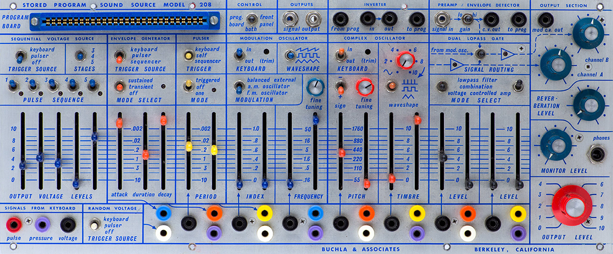
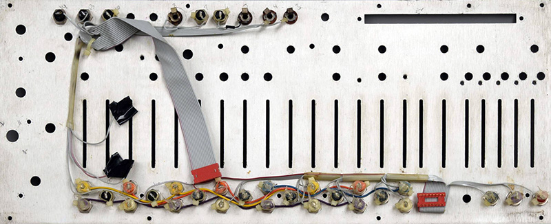
High resolution image of 208 front
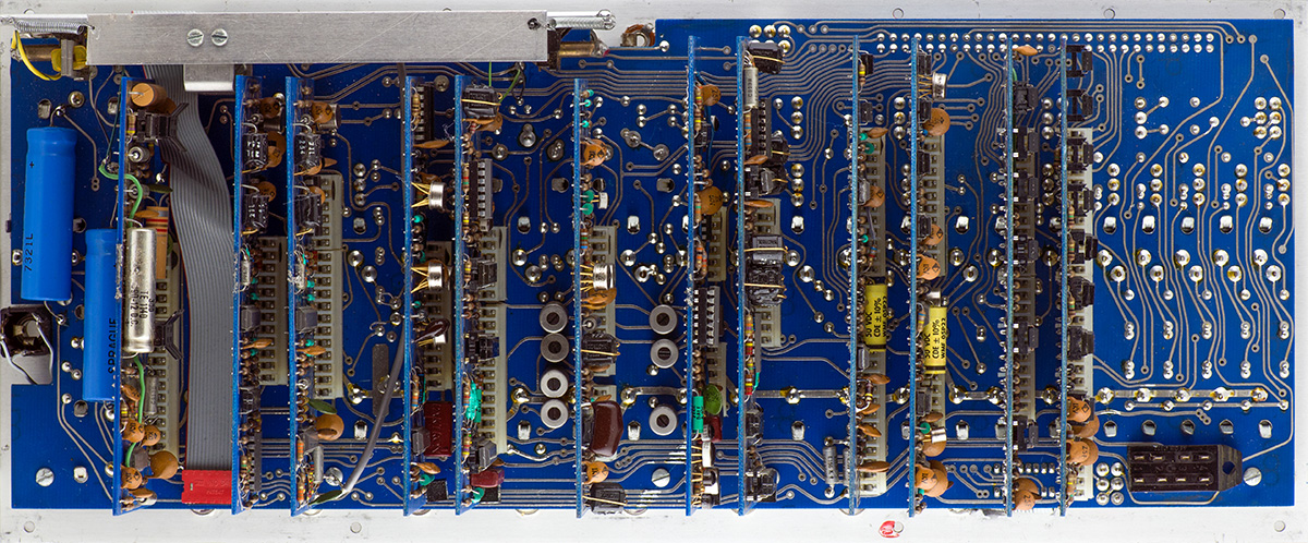
High resolution image of 208 rear
The power header on the motherboard is an 8 pin keyed connector.
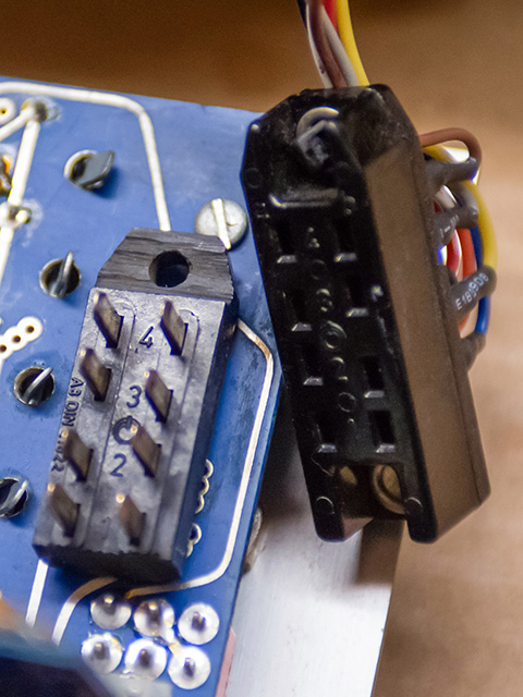
The two ribbon cables connect to the front panel jacks. This photo is not from this 208.
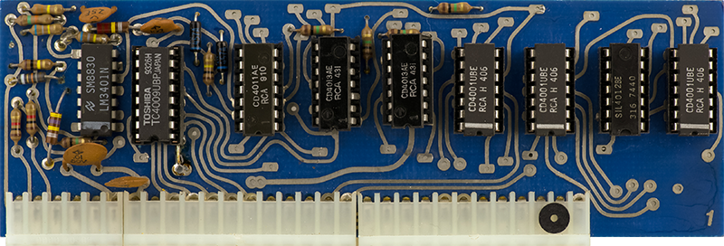
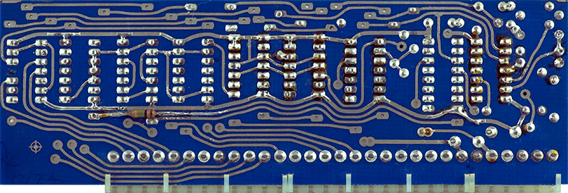
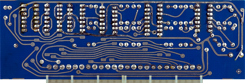
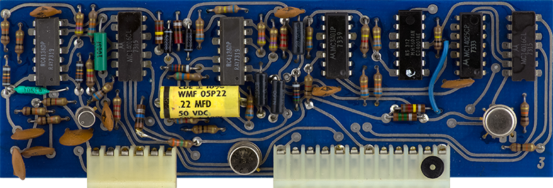
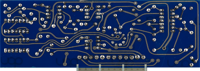
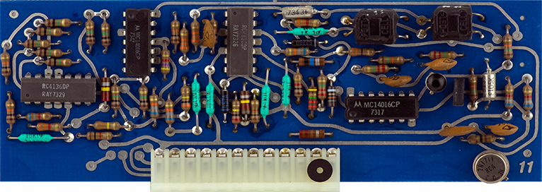
Card 1 is the 5 stage sequencer. The black washers are glued on as possibly a pin 1 marker.
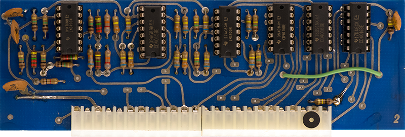
Card 2 is the random voltage source.
Card 3 is the envelope generator
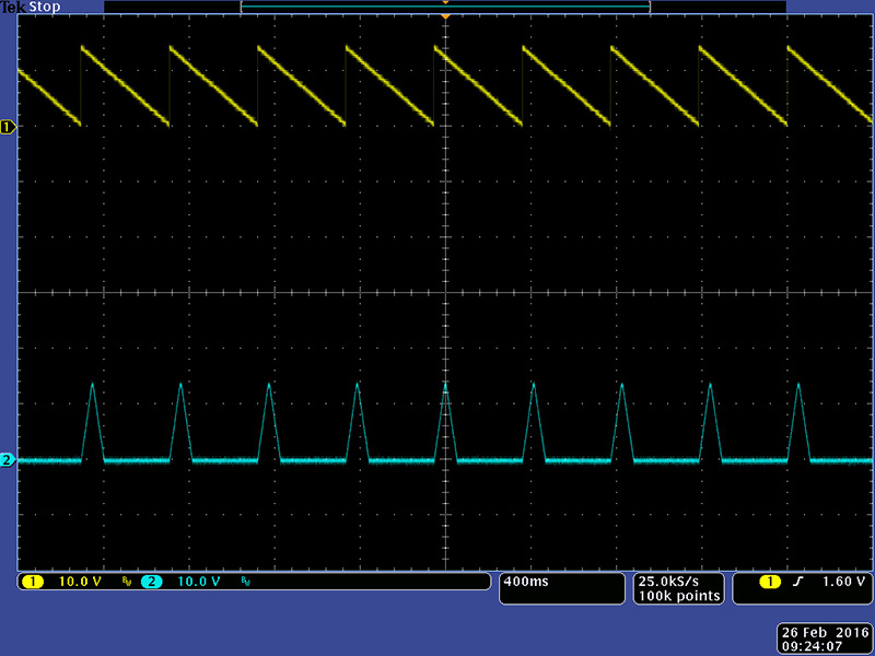
Card 4 is the pulser.

Card 5 is the balanced modulator.
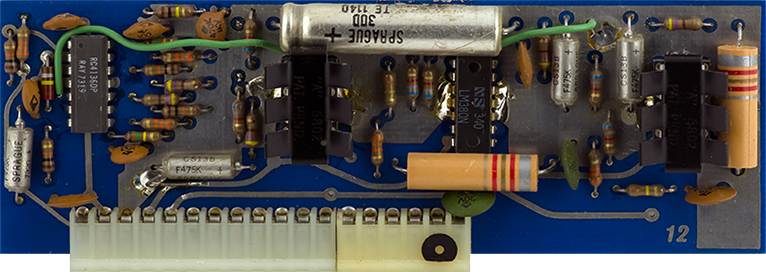
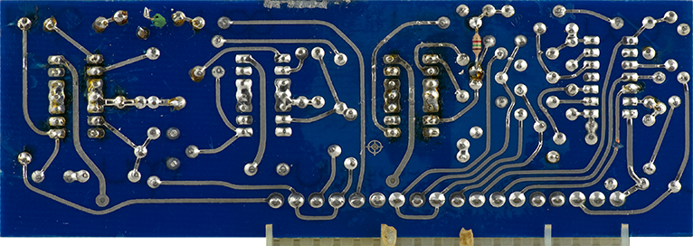
Card 6 is the modulation oscillator.

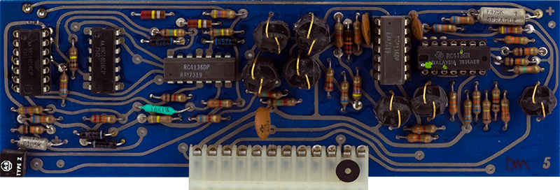
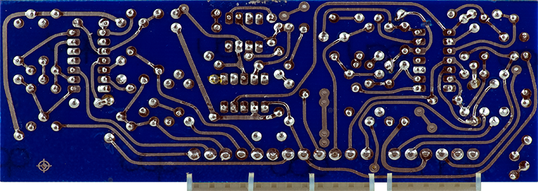
Card 7 is the first of three cards for the complex oscillator.
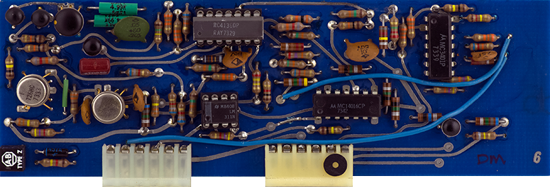
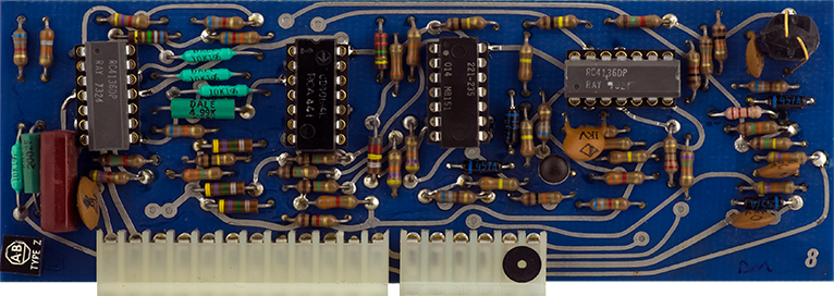
Card 8 is the second of three cards for the complex oscillator.
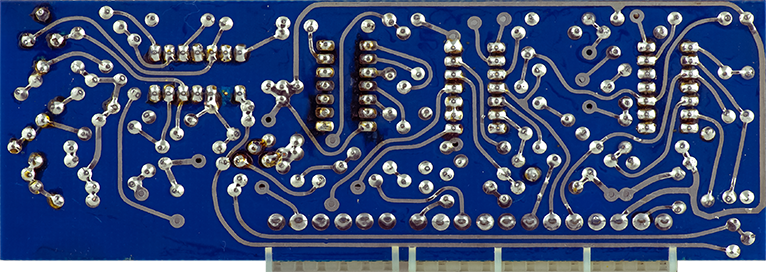
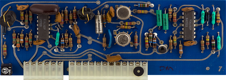
Card 9 is the third of three cards for the complex oscillator. It is actually a second CO that is used to generate the sine wave and the timbre. It is a separate triangle VCO that tracks the CO on Card 8 and is modulated by the triangle output of that VCO when the timbre is increased. The DTL logic gates are driven by comparators and are used to reverse the current of the integrator.
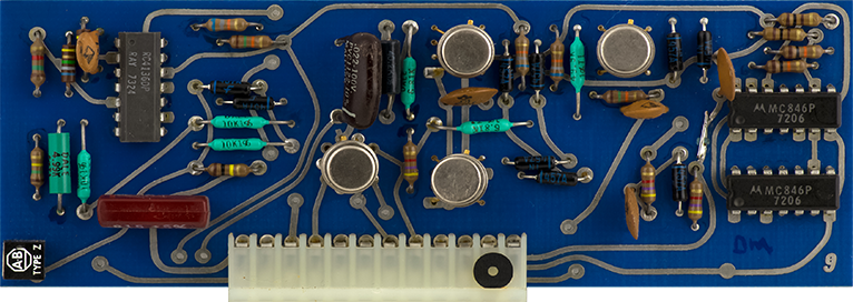
Card 10 is Gate 1 and the Preamp.

Card 11 is Gate 2
Card 12 is the reverb driver and output.
Operation
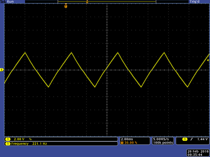
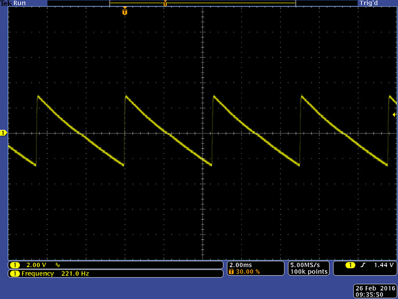
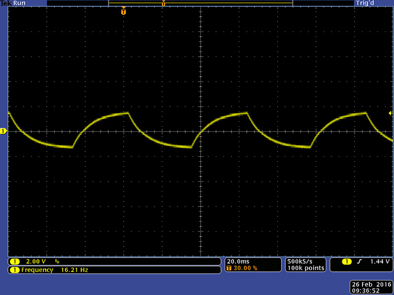
The modulation oscillator operates from 0.13 Hz to 70 Hz with the fine tune control centered. With a CV it can be driven much higher and the waveforms are well shaped.
The square wave has some tilt due to the capacitive coupling.
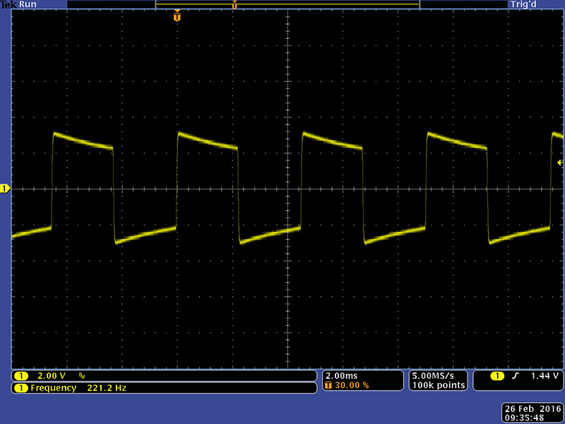
At 16 Hz the modulation oscillator waveforms are quite distorted.
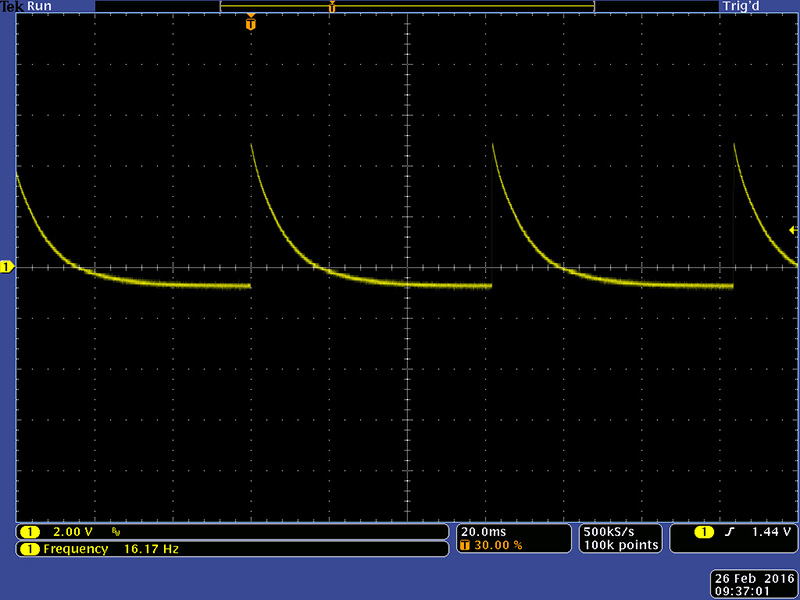
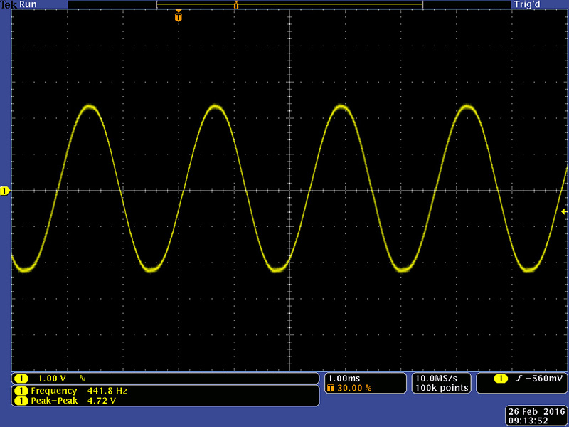
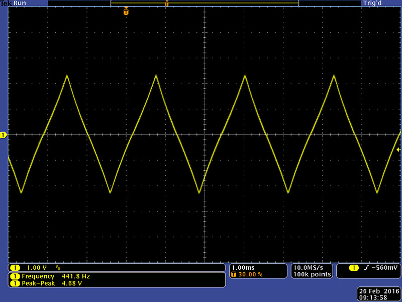
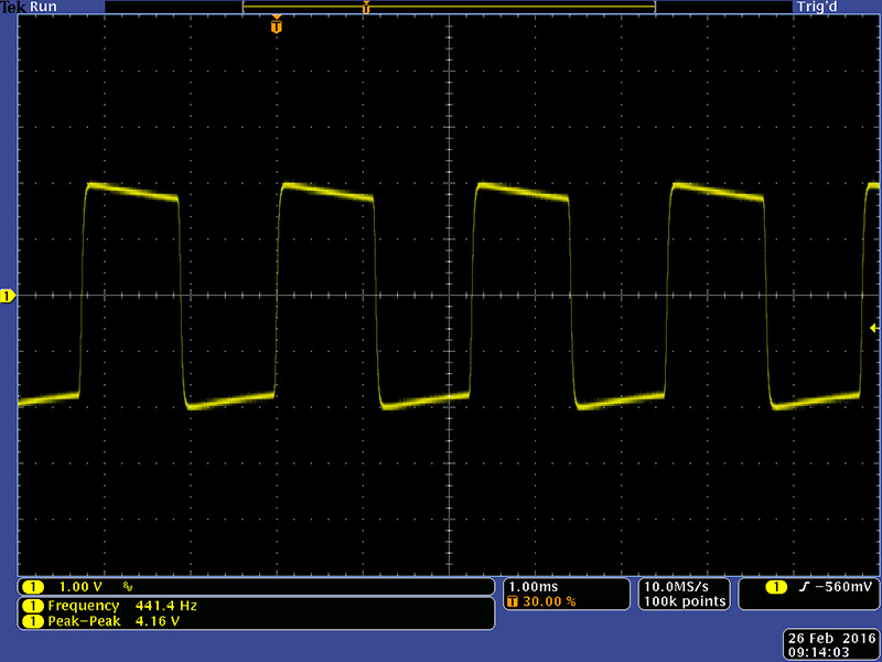
The complex oscillator operates from 38 Hz to 3500 Hz with the fine tune control centered.
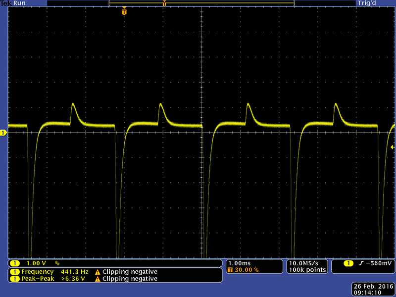
The pulse is a negative narrow waveform.
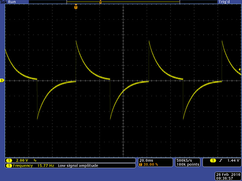
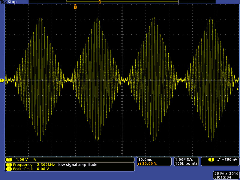
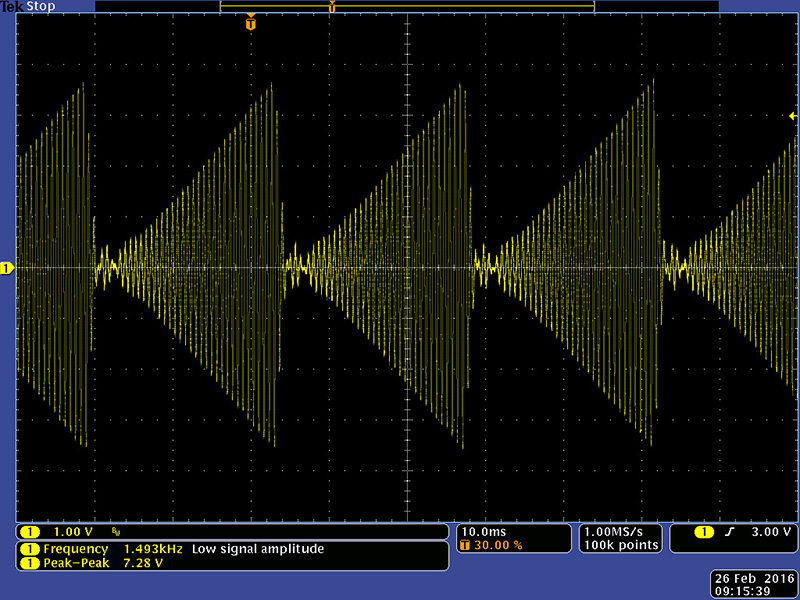
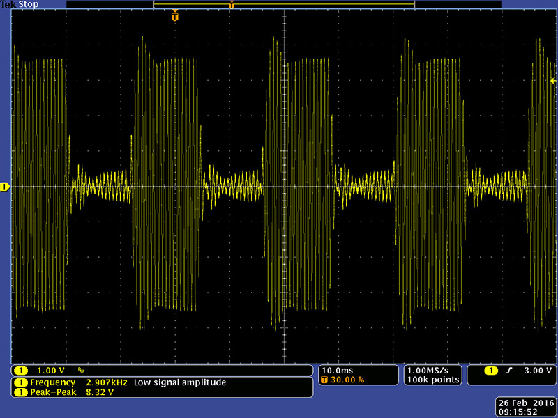
These scope photos are the AM modulation of the complex oscillator with different modulation oscillator waveforms
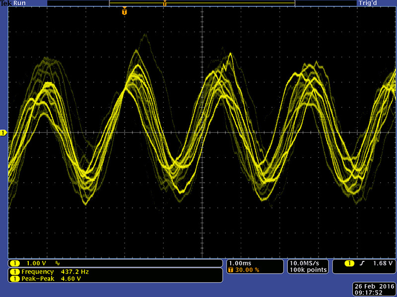
This image shows the complex wavefolding of the sine wave. In the early version of the 208 the timbre circuit is a cross modulation of two triangle waveforms at the same frequency. There are actually two complex oscillators, one is on card 8 and generates the pulse and square waveforms and the other one is on card 9 and generates the sine, triangle, and timbre waveforms.
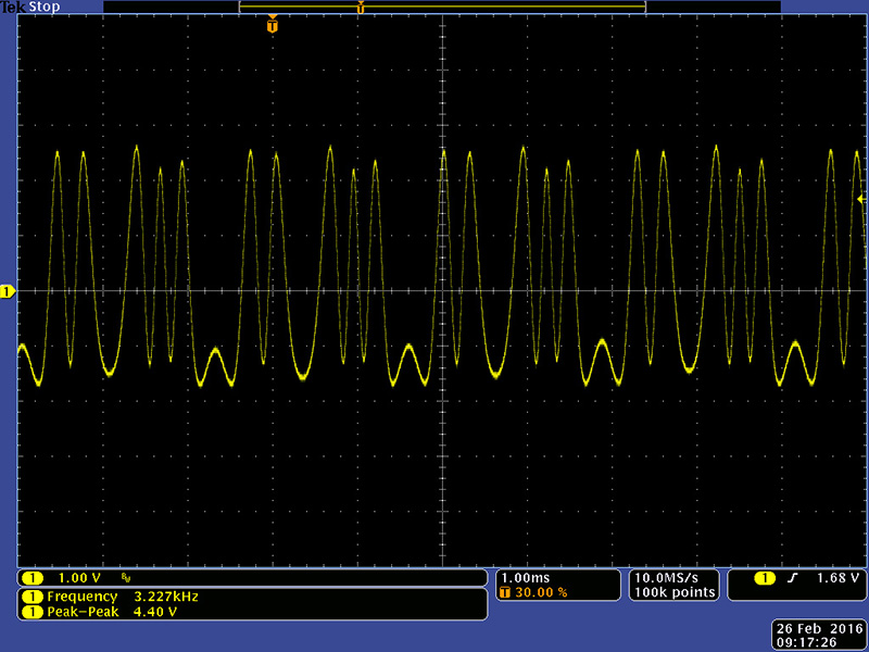
Reverb shows up as just "wiggles" in the waveform.
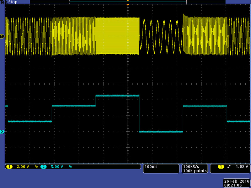
This image shows the 5 stage sequencer in operation.
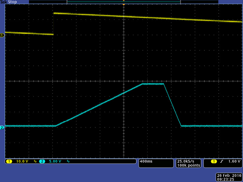
This image shows the pulser driving the envelope generator with an attack, duration, and decay.
This image shows the pulser driving the envelope generator with an attack and decay.