|
CGS Assortment Module |
|
I was asked to build an assortment of CGS boards into a 4U format module. The customer chose a CGS-97 Noise Source, a CGS-88 Bi-directional Triple Switch, and two CGS-578 VCAs. I designed a panel incorporating several modifications for functionality and jack type. I also had to incorporate modifications for Buchla-compatible signal and CV levels.
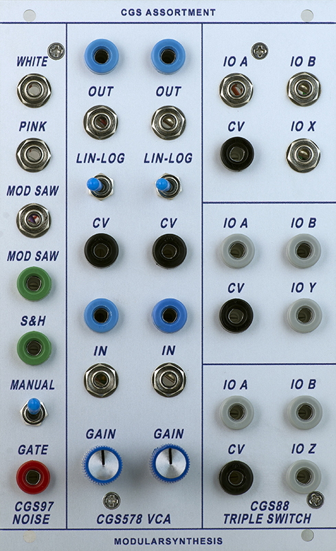
CGS-97 Noise
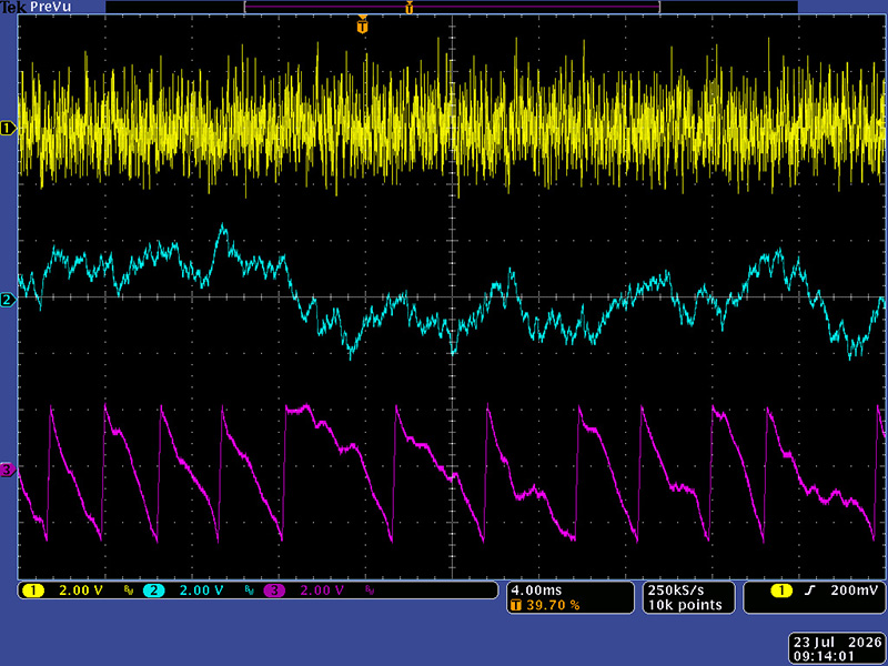
The white and pink signal levels were reasonably close to 4V pk-pk. The modulated saw CV amplitude is 0/+5V. The S&H had some issues and I needed to increase the amplitude and make it a unipolar output. I replaced the CA3130 op-amp and eliminated the transistor follower for improved performance.
This photo shows the white, pink, and CV mod saw.
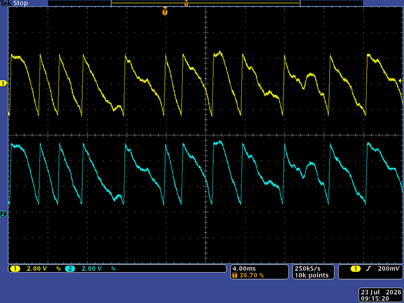
This photo shows the audio mod saw and the CV mod saw. The CV mod saw has an amplitude of 5V.
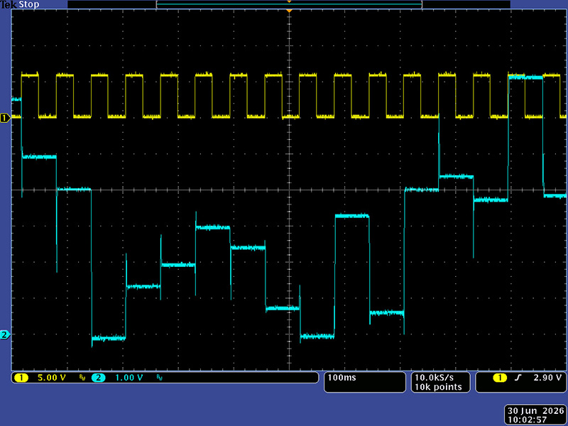
This photo shows the unipolar S&H. The glitches on transition are the tracking and <2 mS.
CGS-578 VCA
This module was based on a Serge design so no schematics were available. I needed to modify the Log and Lin CV inputs for 0 - 10V scale and unity gain for a 4V pk-pk audio signal and 0/+10V CV input as this VCA will operate with either an AC or DC input. The 3.5mm In jacks are for audio and the banana In jack is for CV. The two output jacks are simply in parallel. I came up with an op-amp input circuit for both, but the resulting offset in the CV with no input was addressed by eliminating both inputs and using a switch to select Lin or Log operation. This photo shows the added CV buffer op-amp.

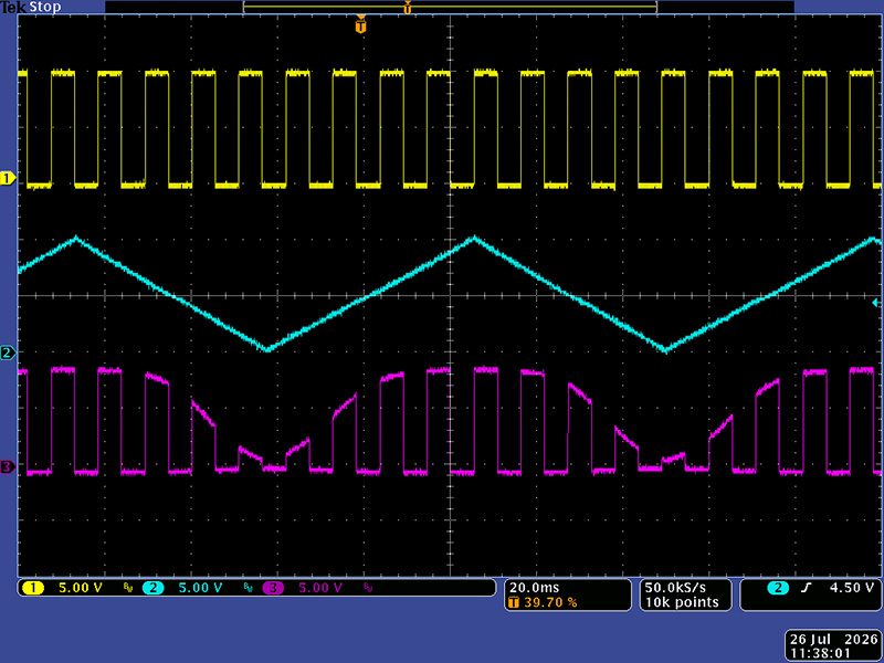
These two images show the VCA with an audio input in Lin mode then Log mode.
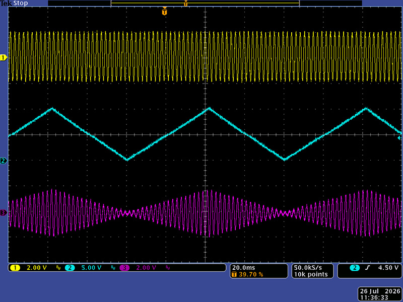
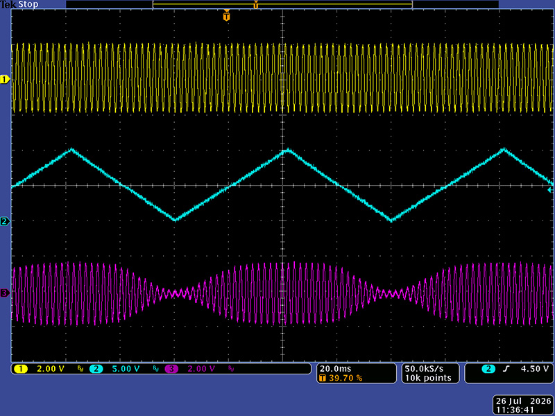
These two images show the VCA with a CV input in Lin mode then Log mode.
CGS-88 Bi-Directional Triple Switch
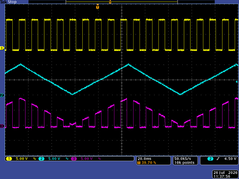
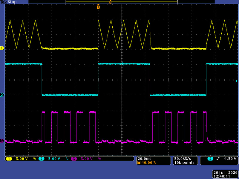
This module was designed for audio signals. I modified two of the channels to operate with 0/+10V CV signals by modifying the supply voltages and logic circuitry. This photos shows switching CVs. There is a minor amount of bleed in the off channel.
Construction
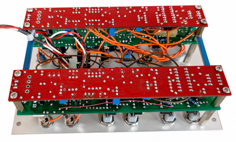
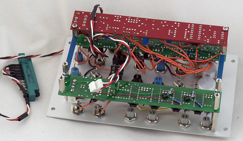
Due to the density of the controls, switches, jacks, and legends I was only able to have two mounting screws for two modules. I mounted the CGS-97 on the left and the CGS-88 on the right. I stacked the CGS-578 on the rear of each. I wanted to use four mounting screws for durability so added some cross supports for additional strength. This photo shows the construction with only one of the CGS-578 boards wired. I daisy-chained the power cabling and used MTA connectors for easy construction and service. Total module depth is 55mm.
And complete.