 |
4U Dual Waveform Generator Model Tau |
|
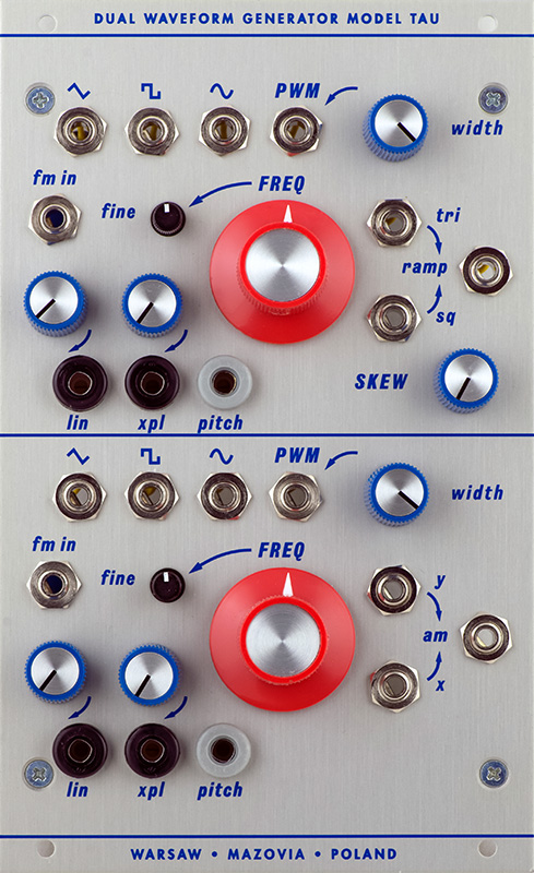
This module is a personal design by Jerzy Przezdziecki. I was sent one for my help by email. The top VCO has an independent analog multiplexer and the bottom has an independent ring modulator.
Construction
The module has a front panel PCB for all the jacks and potentiometers. The majority of the circuitry is on a rear PCB.
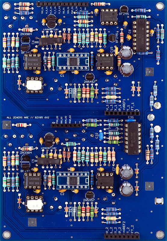
The trimmers are easily accessible from the rear.
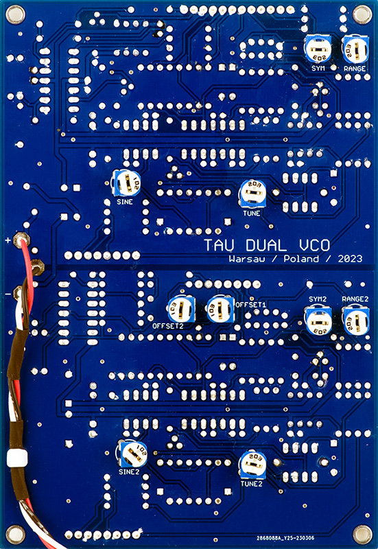
Operation
The waveforms are very clean. The minimum frequency is 10 Hz.
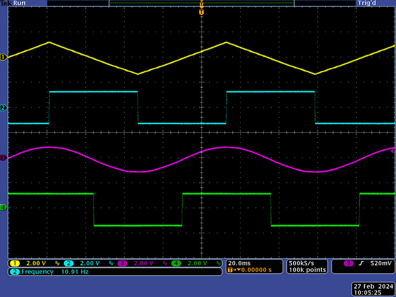
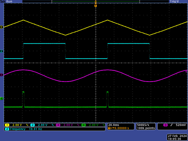
The pulse width is variable from 50% to about 5%.
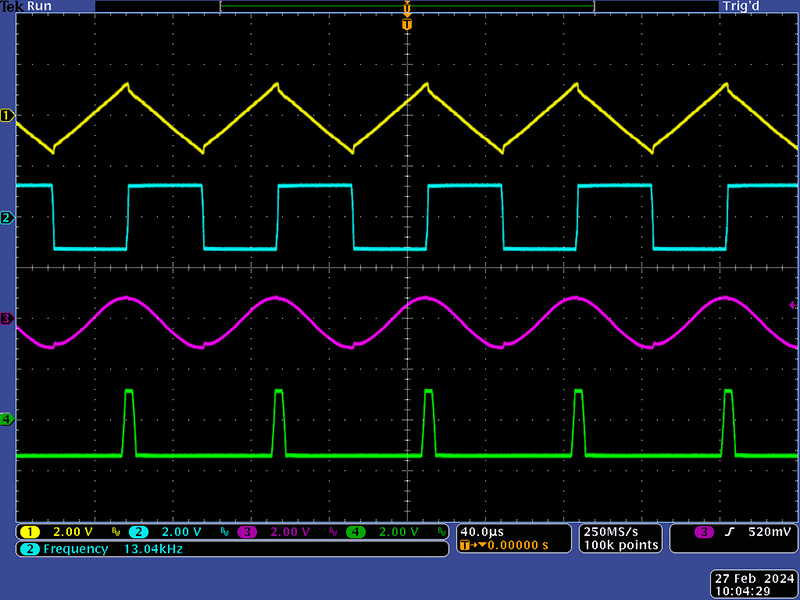
The maximum frequency is just over 13 KHz. Above 10 KHz there is a bit of offset on the triangle which propagates through to the sine.
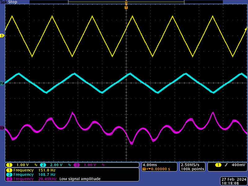
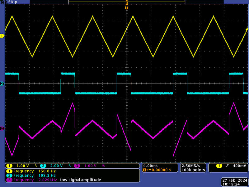
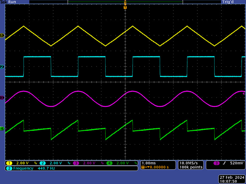
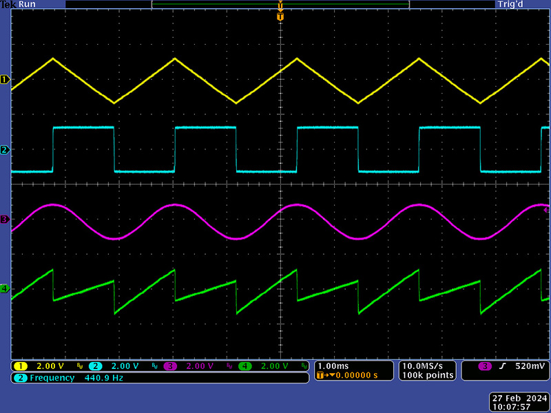
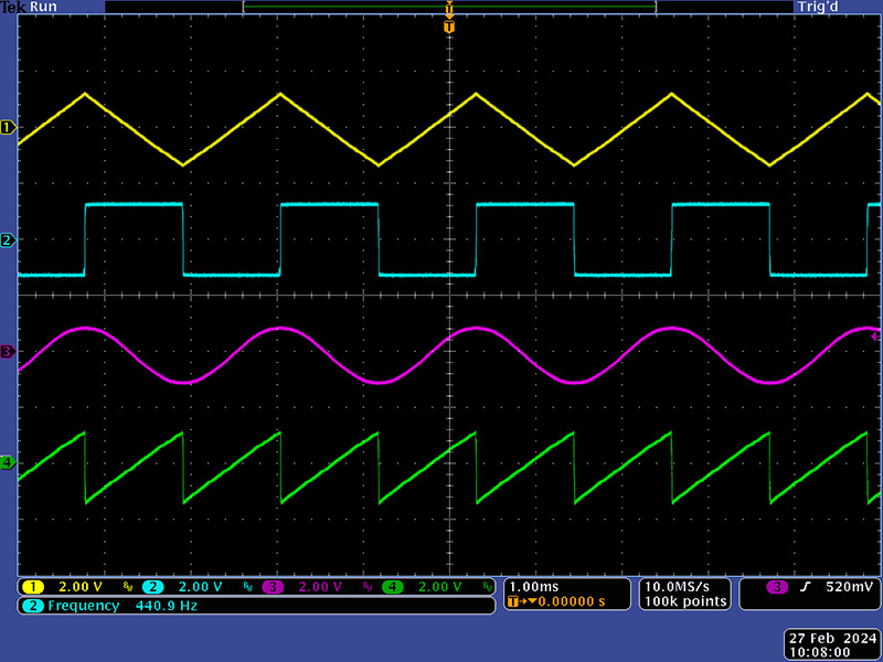
The top VCO has a skew function which takes two inputs. Jerzy describes this as "The upper generator has on its right side an analog multiplexer circuit, which essentially creates a doubled frequency sawtooth waveform, from triangular and square ones. The "SKEW" knob changes the multiplexing value, resulting in the creation of a "rampoid" waveform. Of course, this circuit is not only for that - interesting effects come when you feed other type of waveforms with different frequencies into the "tri" and "sq" inputs! Then the fun begins and the sounds are similar to wavetable synthesis."
With a square and triangle input, this photo shows the resulting waveform with the Skew control at minimum.
This photo shows the waveform with the Skew control at mid position.
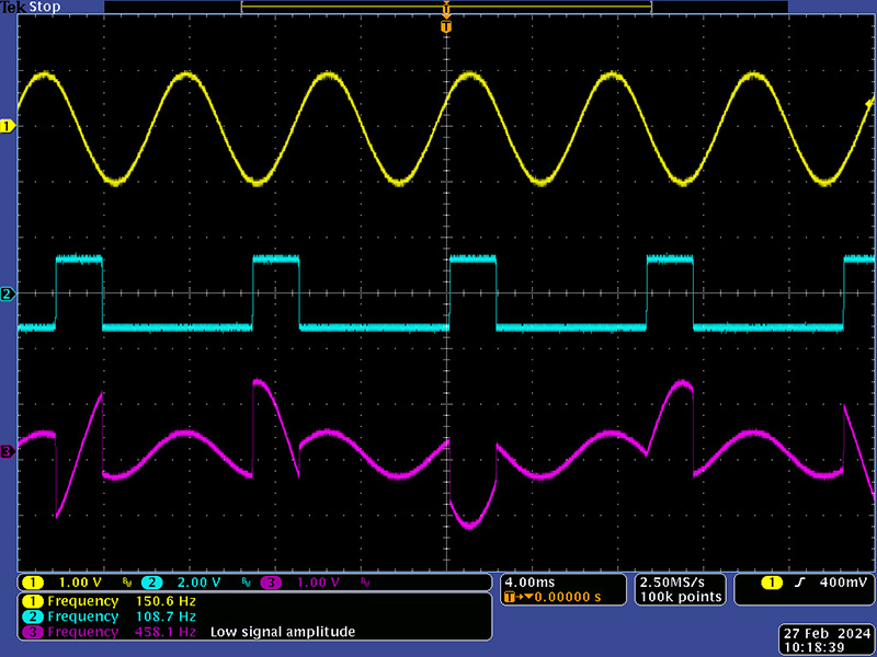
This photo shows the resulting ramp waveform with the Skew control at maximum..
The bottom VCO is identical except the Skew function is replaced by a classic ring modulator built around the MC1496 balanced modulator. Jerzy describes this as "The lower generator has on its right side a circuit for ring modulation/amplitude modulation. This system is original and is not a copy of any existing systems. Its sound has a distinct character different from what we might encounter, for example, in the 285. "x" and "y" are inputs, while "am" is the output. If you want to achieve classic ring modulation, you input sinusoidal signals. Nothing prevents you from inputting signals other than sinusoidal - itís a matter of your imagination."
This photo shows frequency doubling as the result of two sine waves of the same frequency.
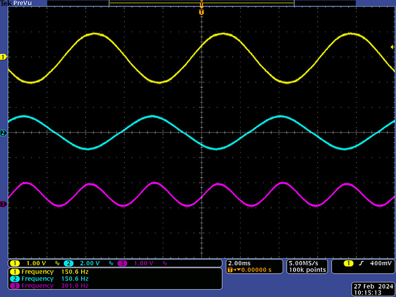
Different wave shapes can be created using different input waveforms. These three photos shows the resulting waveform from using different waveforms at differing frequencies.
