 |
Loft 450 Delay Line/Flanger |
|
I recently repaired a Loft 450 Delay Line/Flanger which uses Reticon BBDs. It was quite a challenge without schematics but I was finally able to obtain a scan of a schematic. I decided since information on the Loft 450 was such a challenge to find to create this page and put all the necessary information together. It has been useful to at least one other owner - "Well I thought you should know one more Loft has been resurrected. Everything works. Thanks."

The AC mains is exposed at the power switch and PCB, fuse holder, and transformer so care must be taken when working on this unit. I covered the exposed mains with silicon.
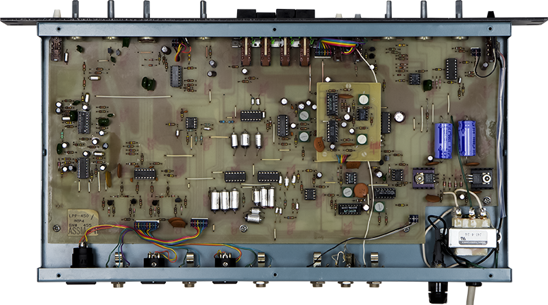
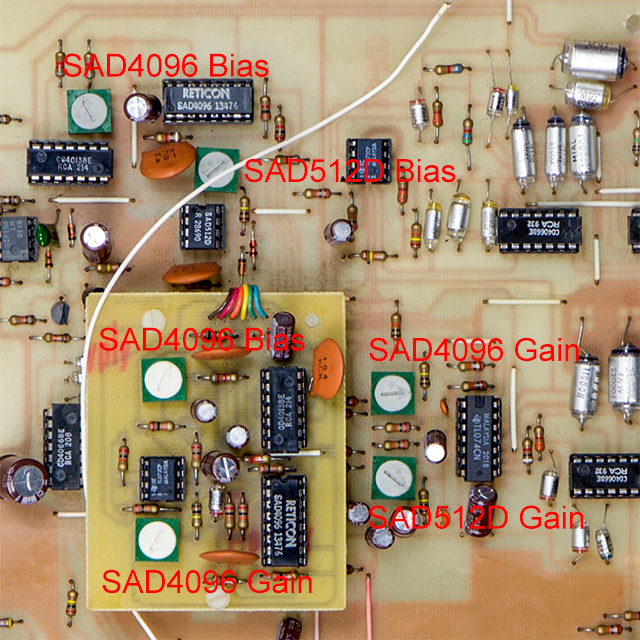
The Loft 450 is built on a single sided PCB. The daughter PCB is the EM-450 with a second SAD4096 BBD.
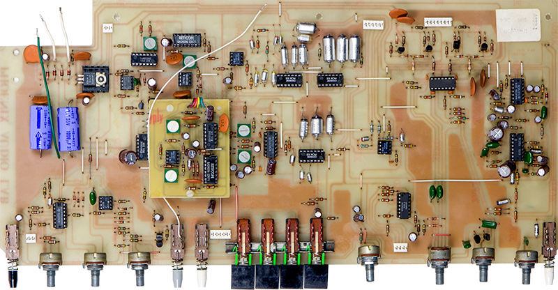
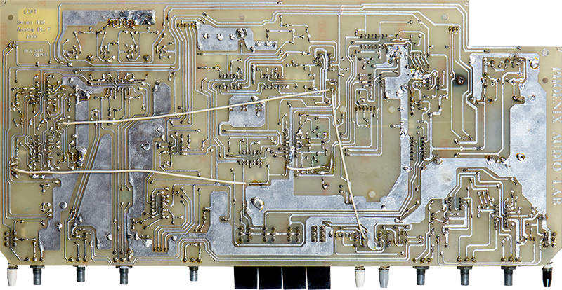
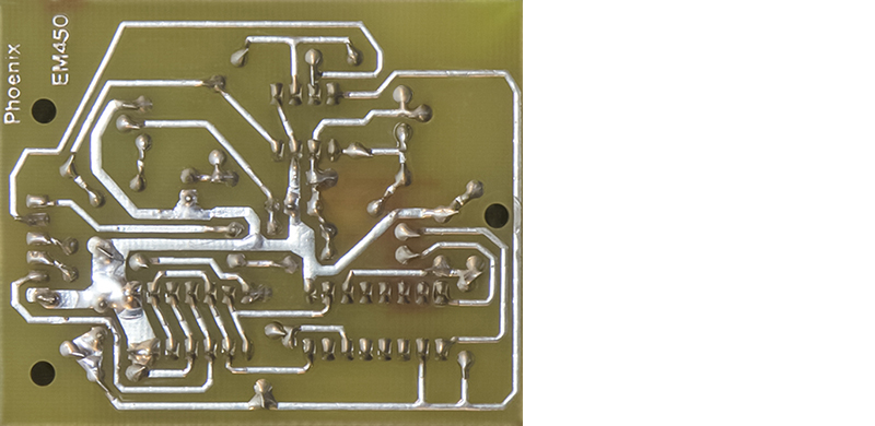
I used the rear image to be able to trace the runs on the top. The ICs are not numbered on the schematic so you have to trace the runs to find the right IC. There are a number of cut runs and jumpers on the rear of the PCB.
The EM-450 daughter board appears to be a simple clock divider, driver and bias, BBD, and recovery amplifier circuit.
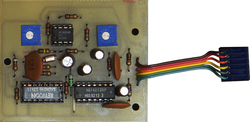
There are bias and gain trimmers on the main PCB and the EM-450 daughter board.
Loft 450 Delay Line/Flanger Owner's Manual
Loft 450 Delay Line/Flanger schematic
The schematic does not include the EM-450 daughter board but it appears to be just a clock divider, driver op-amp with bias trim, BBD, and a recovery op-amp with gain trim. Here are the datasheets for the unique ICs.
NE572 Analog Compandor datasheet
From the R5106 datasheet
I replaced a number of bad parts and got the unit working nicely for delays/echo but not flange since the SAD512D was dead. I did find two interesting issues. The first was there was a nicely done factory-looking modification that bypassed the SAD512D with a capacitor (short white wire on the rear of the PCB just above the delay switches). Removing this wire and a replacement SAD512 from a donor DOD 575 Flanger pedal restored the Loft 450 to full operation.
The second issue was the input resistor to the compressor was replaced with a white wire jumper which caused the compressor to self-oscillate at various frequencies depending on the input signal. Odd that there would be two wiring issues on this PCB. Here is an image identifying the PCB issues.