|
132M Waveform
Synthesizer |
|
The 132 Waveform Synthesizer is very rare as only one was ever built. It is a 32 stage piecewise discrete waveform generator consisting of a high frequency VCO and 32 individual level controls to set the voltage for each of the stages. This is the M.E.M.S. version and more information can be found on their 132M Waveform Synthesizer page. In addition the entire Source Of Uncertainty Episode 6: 132 and M.E.M.S. podcast is devoted to this module.
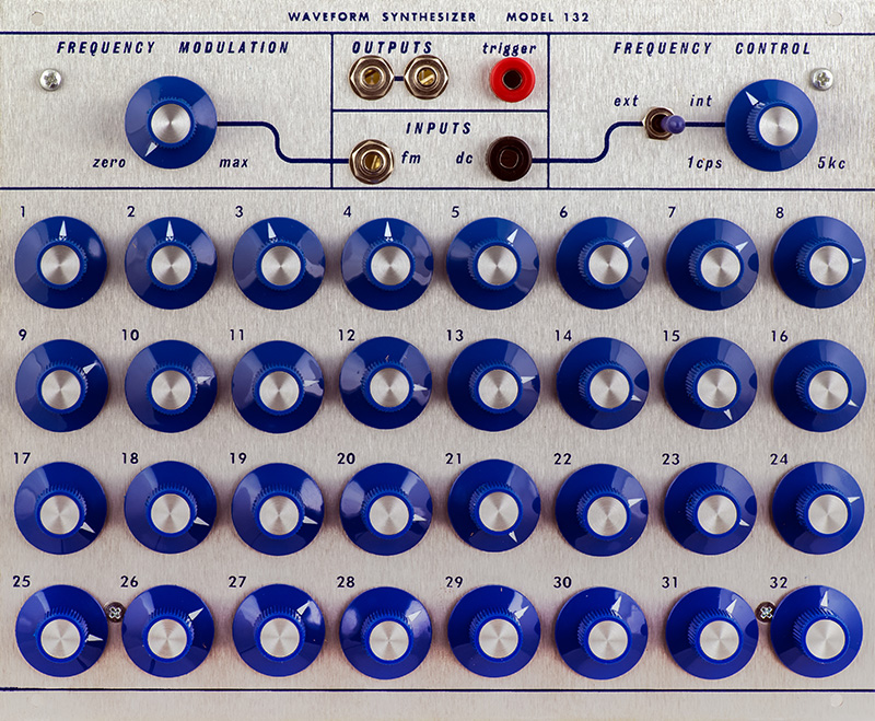
The VCO core is built around a unijunction transistor. The front panel legends would indicate it has the range of 32 Hz to 160 KHz. This frequency is then divided by 32 using 5 two transistor multivibrators. The last two dividers in the chain provide the row drive. The Q3, Q3, Q4, and Q4 signals drive four discrete transistor AND gates which power each row of potentiometers to approximately 11.5V.
The first three dividers provide the column enables. The Q0, Q0, Q1, Q1, Q2, and Q2 signals drive eight discrete transistor NAND gates which selects the appropriate column. Series diodes are appropriately biased and reversed biased to select the specific potentiometer to set the voltage for that stage. This voltage is then buffered and filtered for the final audio output.
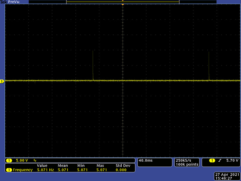
This range is fairly large for a unijunction so Don used some tricks to get this spread. At 5 KHz the period is 200 µS. This module has a Trigger Output indicating the start of the waveform and is the differentiated output from the last divider so has an RC decay. The trigger should be less than half and a 100 µS trigger pulse is pretty narrow. In addition with a fixed output filter the individual controls don't have much effect at 5 KHz so I chose to keep the 132 in the range of 5 Hz to 2500 Hz. A trimmer sets the minimum frequency.
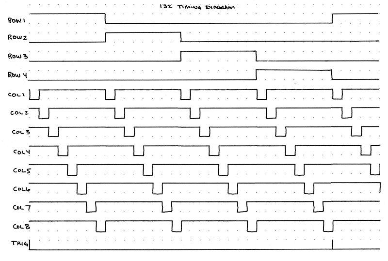
This diagram shows the concept of the clock dividers. The logical combination of Q0, Q0, Q1, Q1, Q2, Q2, Q3, Q3, Q4, and Q4 signals create 32 separate states or stages. The multivibrators clock on the negative transition.
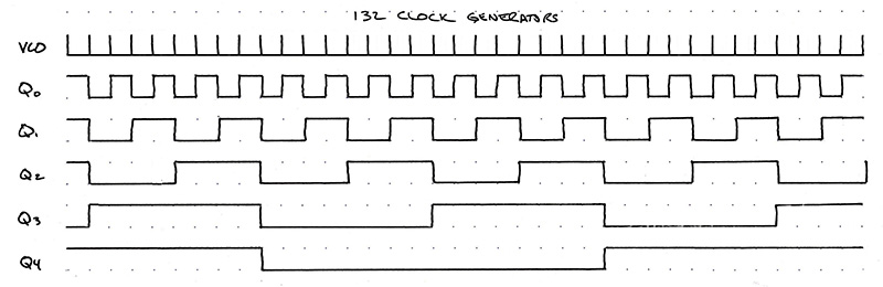
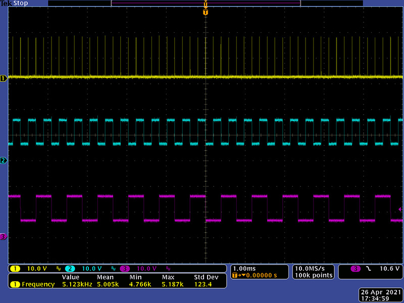
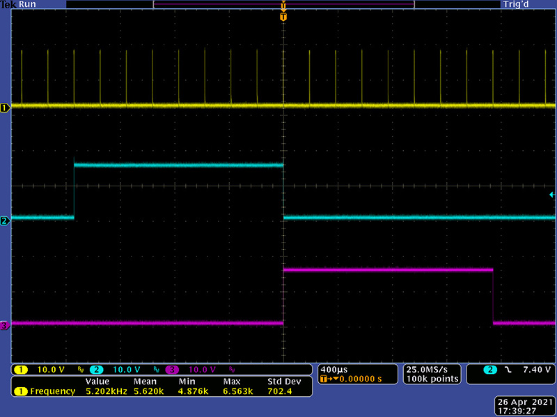
Here are the actual Q0 to Q4 signals as divided from the VCO clock. This is the VCO clock, Q0 and Q1.
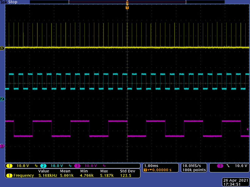
This is the VCO clock, Q0 and Q2/
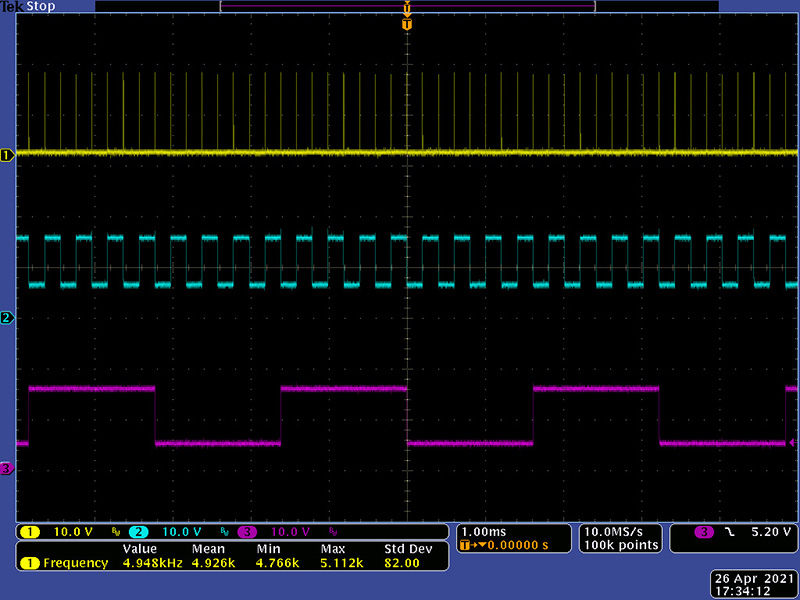
This is the VCO clock, Q0 and Q3.
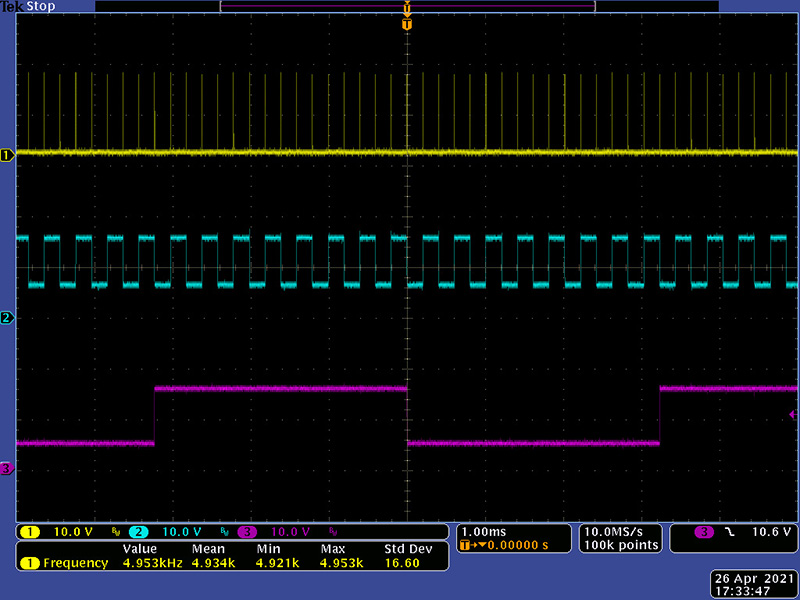
This is the VCO clock, Q0 and Q4.
This diagram shows the concept of the row and column timing signals. The column pulse negative voltage level is the level as set by the potentiometer.
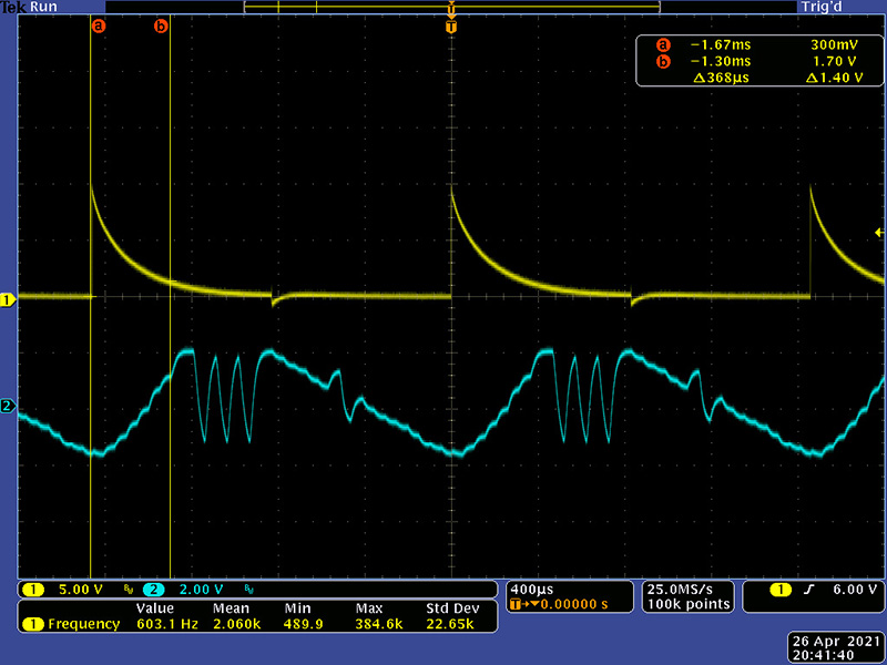
These are Row1 and Row2 drive signals for the top two rows of potentiometers. They are the outputs of the AND gates and you can see the 8 VCO pulses for each row.
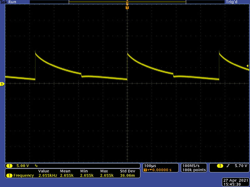
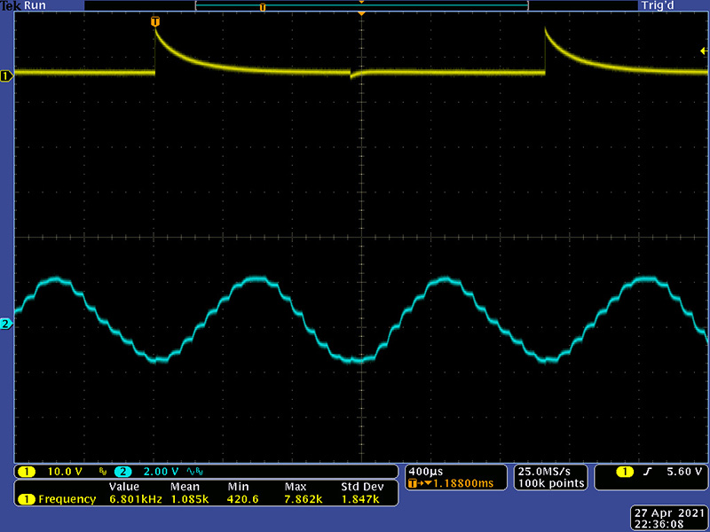
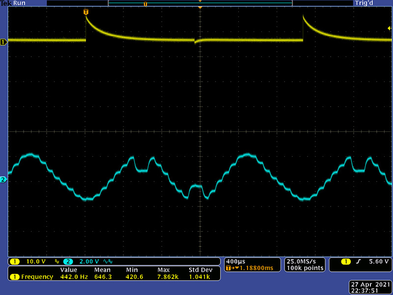
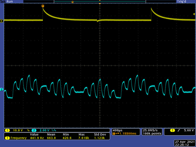
Here is the Trigger and a synthesized waveform Output. The Trigger is a 370 µS 10V pulse at the start of the waveform. The period is 1.66 mS so there are approximately 8 stages per division which can be seen in this waveform. The fixed output filter smoothes the square edges at higher frequencies.
Operation
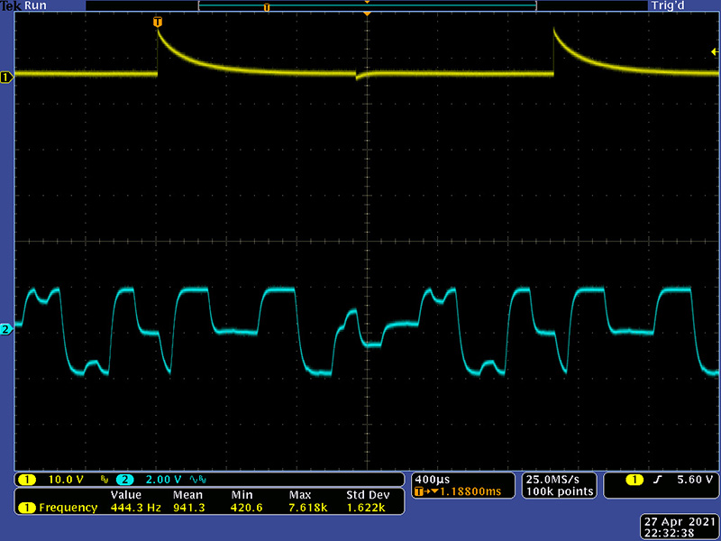
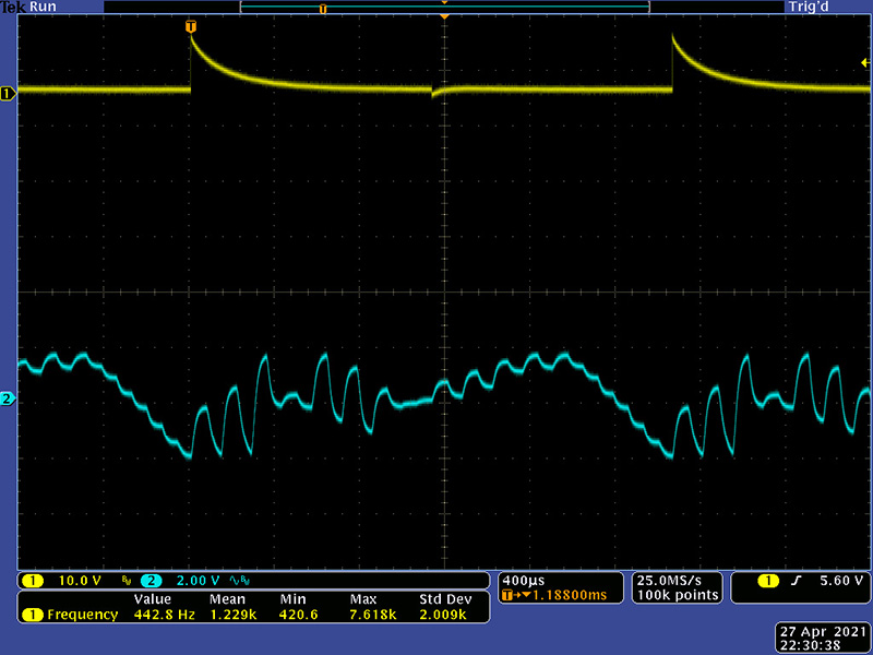
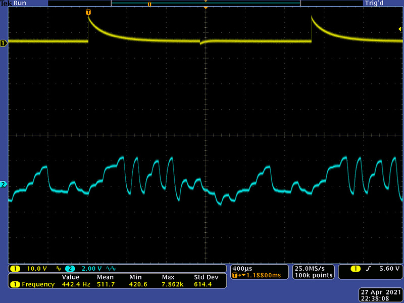
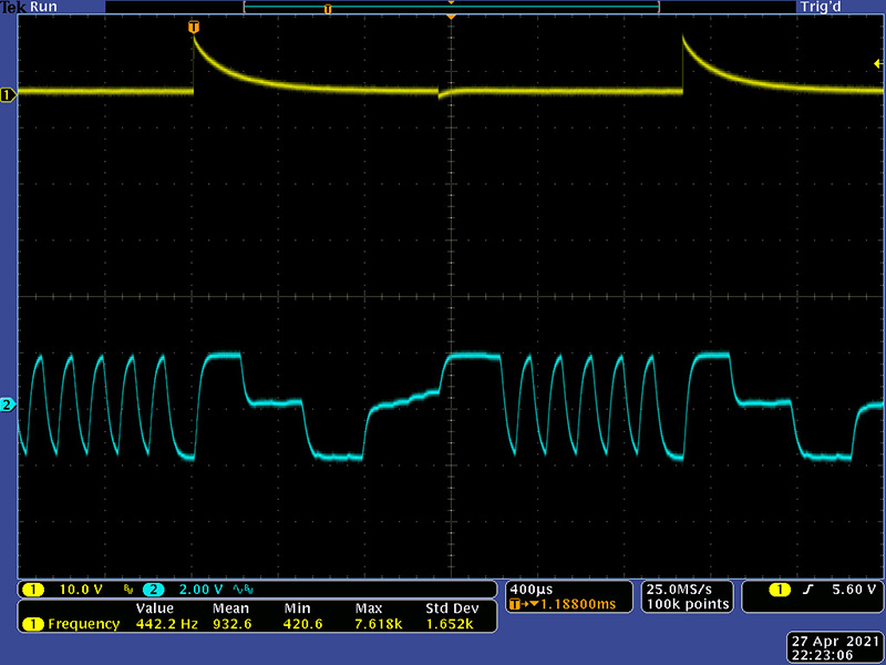
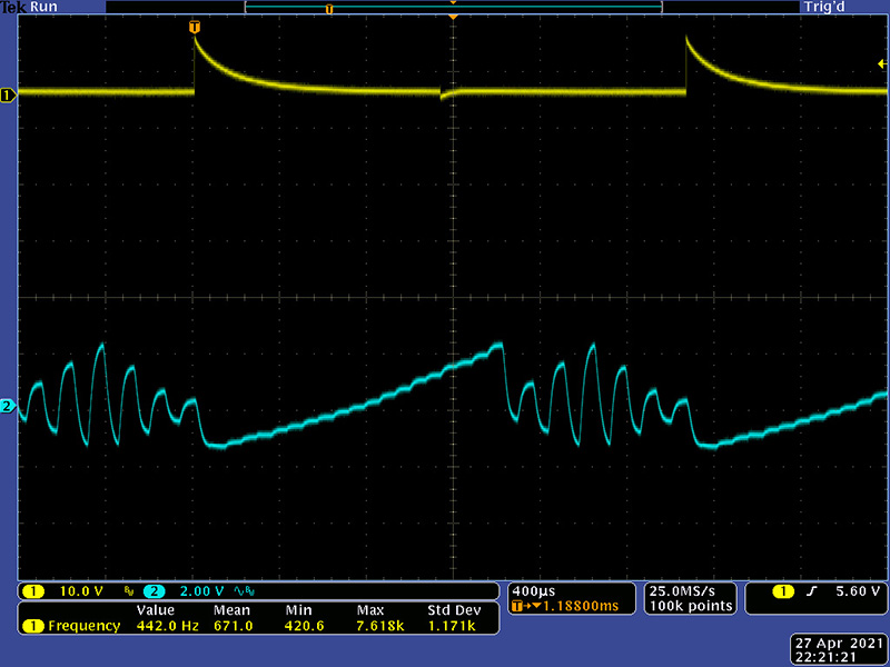
This is an interesting module to use as 32 controls are a lot to adjust. Here are some various waveforms I generated with this module. Its interesting to hear the harmonics change as you adjust a single control. This first one was interesting in that as I adjusted it more towards a sine the harmonics gradually disappeared and the sound became more "pure".
This M.E.M.S Vimeo video shows the 132M in operation.