|
207M
Mixer/Preamp |
|
I built a 207 Mixer/Preamp for a customer with a twist. He did not need the microphone preamp but wanted an effects loop. I repurposed the microphone jack as a stereo send, added a 1/4" stereo return jack, repurposed the control as a wet level, and repurposed the Preamp output jacks as a non-attenuated wet left and right jacks.
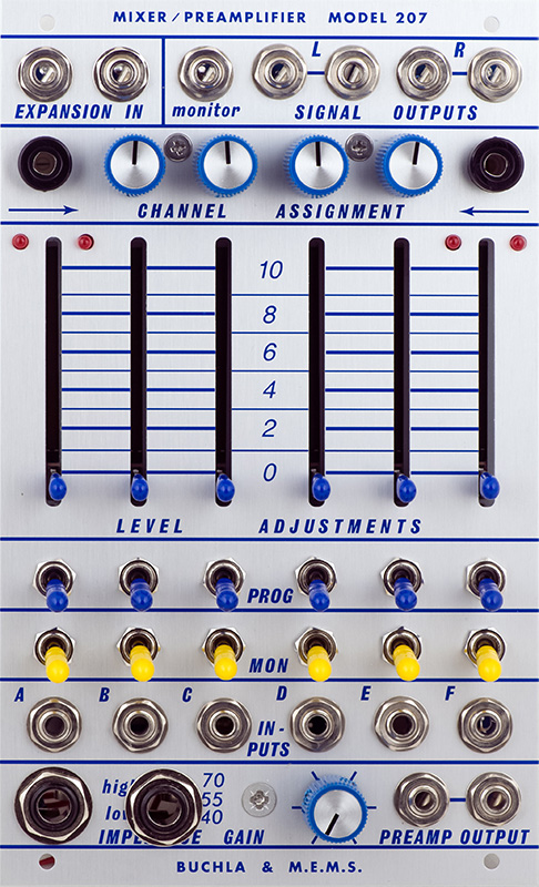
I tried making a label to cover the impedance and gain legends. At straight on it looked somewhat reasonable, but at any angle the sheen was different enough that it really stood out.
Construction
I cut the PCB to accommodate the extra jack. The normal 207 outputs become the dry send, but attenuated by 50%. I repurposed the microphone preamp as the wet-dry mix with a wet gain of 2X. If you leave the wet return gain at minimum, then the main outputs become the dry outputs and the Preamp jacks become the wet outputs.
I matched four MEMS vactrols. The added resistors on the rear of the PCB match the gain of channels 1 and 6 to that of 2 - 5. Because I matched the vactrols all four resistors are the same value.
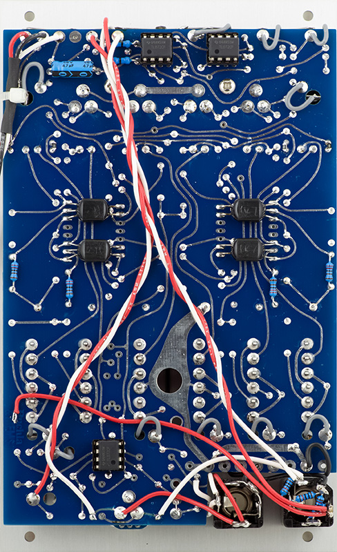
The one wire pair to the right are the normal outputs which go to the resistors on the send jack to attenuate, and also to the new output mixer. The other wire pair going to the left connect to the output jacks and go to the new output mixer. I was able to reuse most of the component placement for the new parts values and needed a few trace cuts, especially around the control.
I needed a stereo 9mm control and used an Alpha dual potentiometer. I only had to run 2 wires to it which fit nicely.
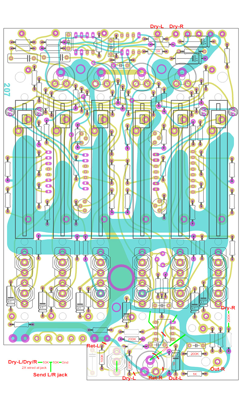
This is the mod sheet I created for assembly and wiring. Components not installed are faded out, trace cuts are red, and wire links added are green. Bold labels show what wires connect to the various jacks. Regular labels show value changes.
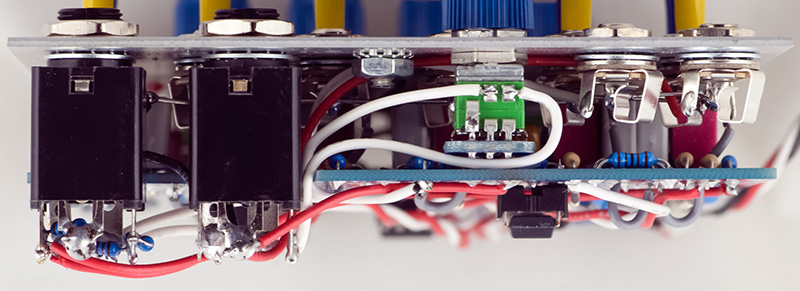
It all came out quite nice. I don't have any photos of the component side PCB as the final assembly was to solder just one pin of two switches to the PCB for alignment and then sandwich the PCB, switches, wires, and panel together. That took a bit of work to get all the wires positioned correctly and I wasn't going to pull it apart again. The LEDs did not fully extinguish so I did add the 10K SMT resistors as I have before. It was a bit confusing trying to keep left and right matched correctly for the main outputs, Send and Return (ring=R, tip=L), and Preamp jacks but I used red for right and white for left.