 |
227M System
Interface Module |
|
The 227 System Interface is quite a versatile module and is fairly complex but is not well documented. I did find some documentation in a Buchla Synthesizer User Guide written by Daniel J. Scheidt dated November 16, 1981.
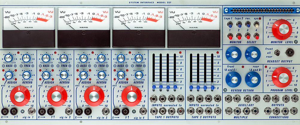
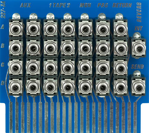
The right top corner has a 44 pin connector that mates with a plug-in card. The plug-in card has output jacks for program A-D and monitor A-D. There are input jacks Tape 1 A-D and Tape 2 A-D which connect to the Tape Output jacks and are normalled to the Tape Input jacks. The Aux 1 A-D and Aux 2 A-D jacks connect to the Auxiliary Output jacks on the panel. There are jacks for reverb Send, reverb Out (from tank labeled INT), and Reverb returns A-D. The INT must be patched to one or more reverb returns.
The reverb return controls mix the mono reverb signal to the front channels B & D or the rear channels A & D.
There are four independent mono input sections each with a separate level, bass, treble, reverb send and assign control. Assign pans the channel to program A, B, C, or D. Program A and D are the rear channels and B and C are the front channels. There are two CV inputs, X and Y, which will pan the signal from front to rear (A>B) or left to right (A>D).
The tape section is comprised of Tape Output jacks which are directly connected to the expansion card Tape Input jacks and normalled to the panel Tape Inputs jacks just above them. Inserting a plug into the panel Tape Input jacks on the panel breaks the connection to the Tape Output jacks and the expansion card Tape Input jacks which are still connected. The sliders attenuate the Tape Input signal.
The 227 Document says "Dubbing from one machine to another is then simply a matter of playing a tape on tape 2, setting the desired levels with tape 2 slide pots, and then recording on tape 1. Since the inputs are normalized to the outputs, no patching is required as long as no processing is needed." The inputs to the tape decks are from the Monitor Outputs on the expansion card. The Monitor Outputs are like "line outputs" which are the pre-level Program Outputs. The outputs of tape deck 2 are connected to the Tape 2 In on the expansion card which connects to the bottom row Tape 2 Output jacks. These are normalled to the Tape 2 Input jacks above and with the sliders set appropriately connects them to the Program bus. Tape 1 Input Levels need to be off to prevent a feedback loop.
The Multiples are groups of four jacks wired in parallel. The Auxiliary Outputs are wired to the Aux Inputs on the expansion card.
The monitor select switches patch the selected input to the monitor bus. The monitor bypasses the input levels, assign and tone controls on the mono input sections and the input attenuators on the tape inputs. The Sys switch monitors the external MTS signal on the interface cable. With no MTS signal this effectively mutes the monitor bus. The program bus is monitored if all switches are off.
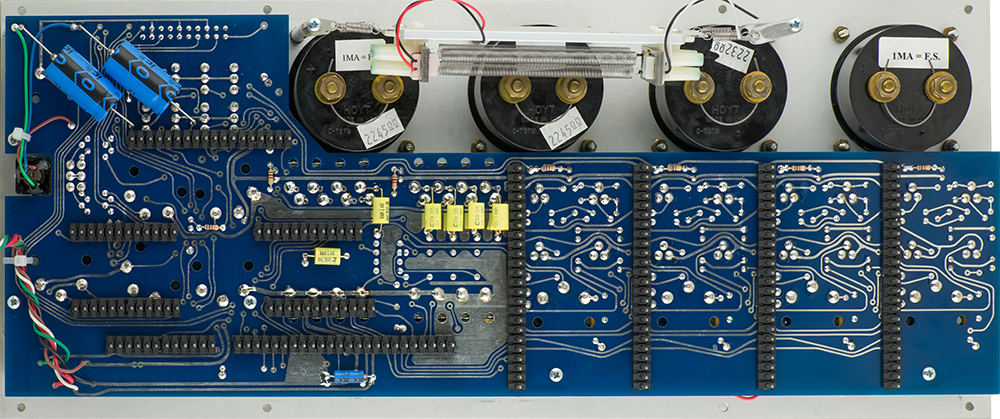
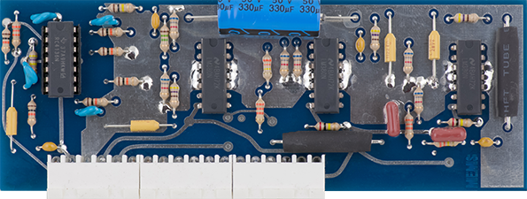
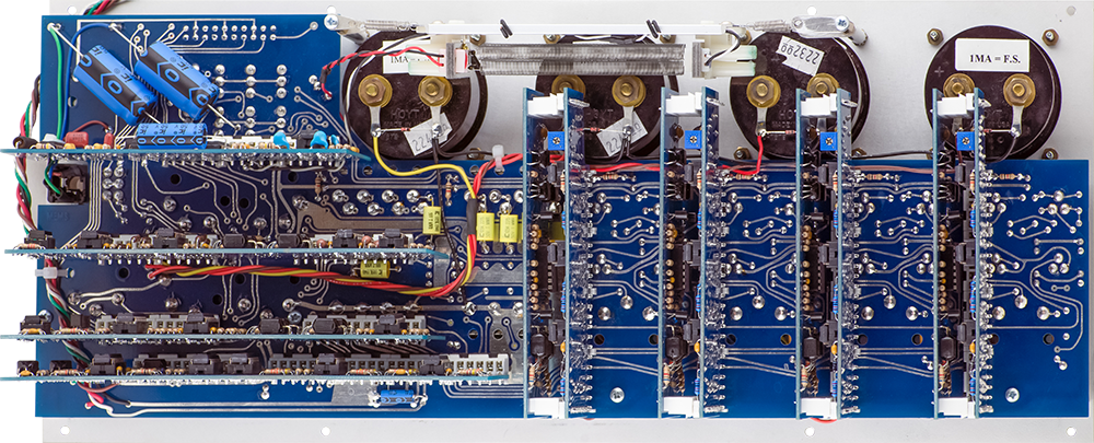
The motherboard has some circuitry for the four mono input channels and but the majority of the 227 circuitry is on the 8 plug-in cards. The meters and reverb tank have not yet been wired to the motherboard.
The four mono input cards consist of two cards sandwiched together.
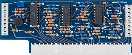
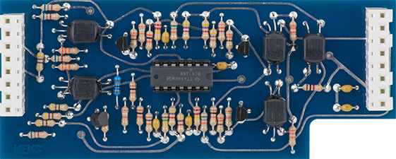
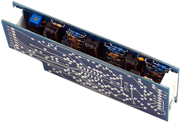
Card 2 consists of the quad tape input buffers and the reverb return. The vactrols are used for the reverb return levels.
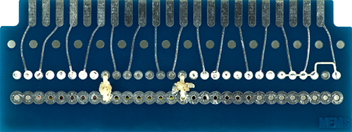
Card 3 is the plug-in IO card consisting of all the jacks. The reverb return is hard wired to all four channels.
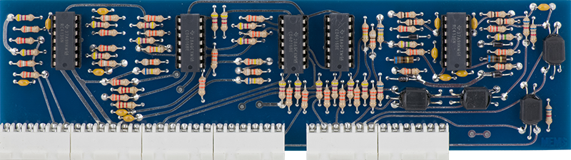
Card 4 consists of the program buffers. The four vactrols are used for the program level control.
Card 5 consists of the monitor buffers. The four vactrols are used for the monitor level control.
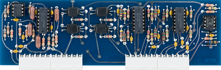
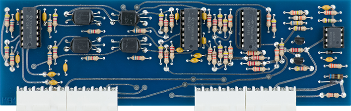
Card 6 consists of the reverb circuitry and is similar to the 208 Card 12.
There is also a plug-in I/O card for direct wiring.
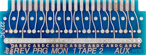
I always wire up the plug-in card to use the front panel Aux jacks. In this day and age, I doubt anyone is really wiring up 8 Aux trunk cables and 8 Tape cables to the program card. This wiring maps the program outputs to the first 4 Aux jacks, and the monitor outputs to the second 4 Aux jacks.
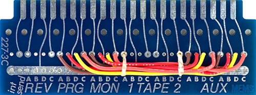
The wiring on the right rear maps the reverb out (from tank labeled INT) to the four reverb returns A-D.
Here is the completed 227 including the meter and reverb tank wiring. I did add Schottky diodes across the meters as a rudimentary form of protection. There is no level controls for calibration of the meters but four resistors can be tweaked to adjust the gain of the meter drive circuit.
Operation
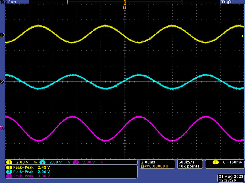
Note that these measurements are with the meters that MEMS selected and other meters may be different. Resistors R29, R31, R33, and R35 can be eliminated or added to increase the gain of the meter circuit. This is using the Monitor Select on channel 1. A 2.48V pk-pk input signal read 0 dB on the meters with a 2.0V pk-pk Program Output and a 3.36V pk-pk Monitor Output. The Monitor Select gain is always a bit hotter than normal.
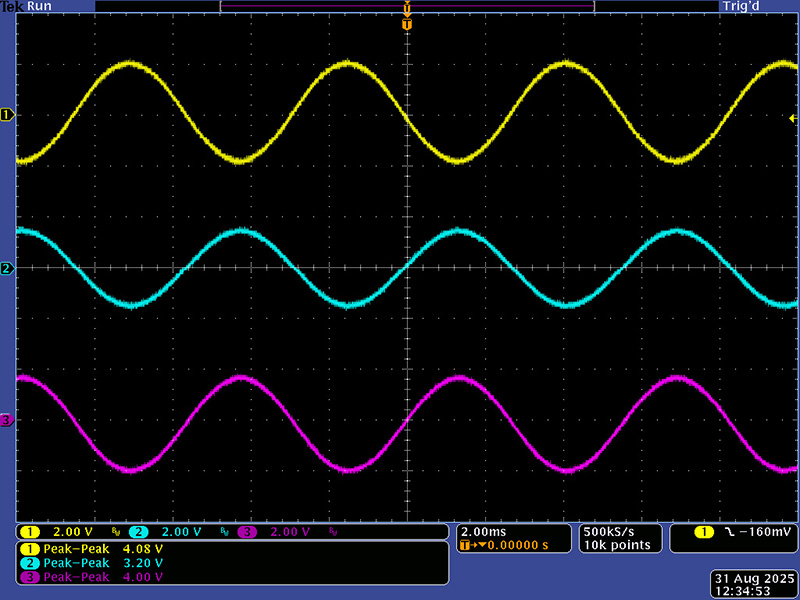
I then adjusted the input signal to 4V pk-pk, turned off Monitor Select, and set channel 1 to maximum gain with the bass and treble controls centered. The Program output is 3.2V pk-pk and the Monitor output is unity gain at 4V pk-pk. The meter read +1 dB.
This module has a lot of vactrols: 6 per input card x 4, 4 for reverb return, 4 for monitor level, and 4 for program level, a total of 36. This unit was built with matched MEMS vactrols for each of the functions and the channels are reasonably matched. The only calibration is for the quadrant adjustment and all four inputs were pretty similar. As you change the assign to B, C, and D, the levels vary slightly due to circuit tolerances and of course the vactrol variability.
The headset output controls can be confusing. They have no legends so one might think they match the reverb return below with a front and rear operation. They are simply left and right level controls, so A and B are assigned to the left and C and D are assigned to the right.
