|
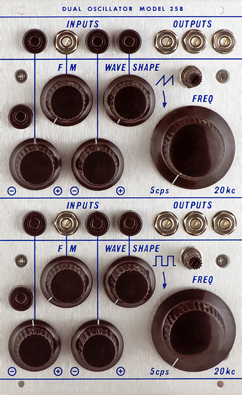
258M-C Dual
Oscillator |
|
I built this MEMS 258C and modified it with a dedicated keyboard CV input matched with the other two CV inputs.
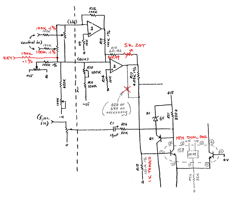
The 258C, as can be seen in this partial schematic, has no scale trimmer and is not setup for 1.2V/Oct. The front panel attenuators can be adjusted for a 1 or 1.2V/Oct scale. In addition it uses the uA726 as the heated expo pair to provide temperature stability.
Many of the these modules add a scale trimmer and and a front panel fine adjust for CV1. I chose to modify this 258 by adding the scale control in the feedback path of IC1 and replacing the CV1 fine trimmer with a dedicated keyboard CV. I used 0.1% resistors for the three CV inputs to better match the channels.
I chose to make R18 a tempco resistor and simply use a NPN matched pair for the expo converter. Since 150R is not a common value, I chose to scale the feedback resistor to be able to use a 1K tempco.
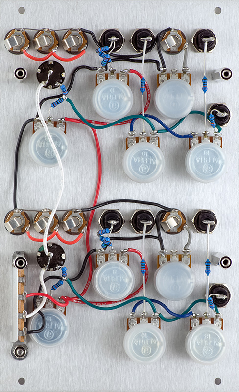
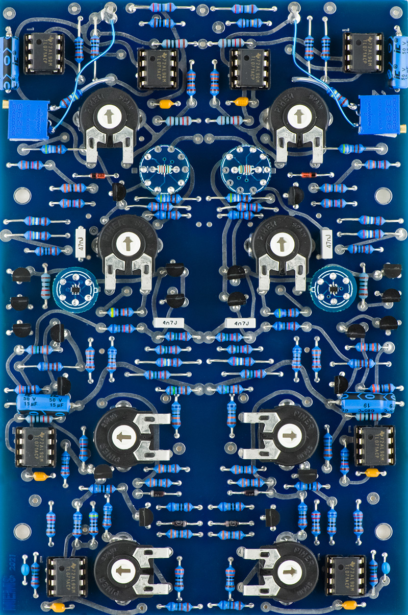
The front panel wiring is complete. I choose to mount the potentiometers with the terminals up to allow more clearance at the bottom edge of the module. for the wires.
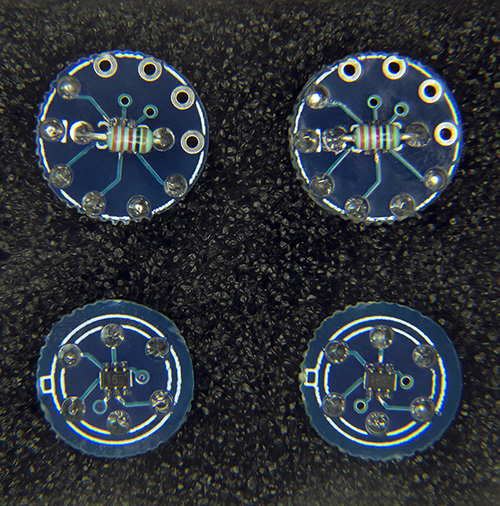
I used a uA726 adapter PCB with a PMP4201Y,115 and 1K tempco with thermal grease for IC3. I used a SMT adapter with a PMP5201Y,115 for Q4 although any matched PNP pair or cut tape 2N3906 transistors would work fine.
I've added the trimmers with double-sticky foam tape so they can be adjusted when assembled. The two jumpers are not yet installed on the PCB.
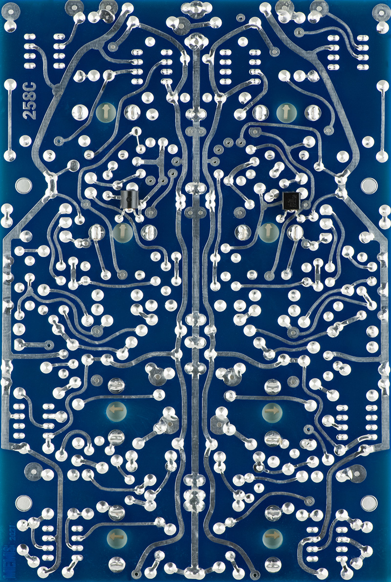
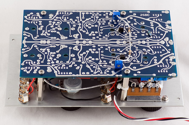
Don added Q12 after this PCB was complete so they are added on the rear.
Calibration
I used cut tape 2N3904 and 2N3906 for the transistors and J201s for the JFETs. The module calibrated nicely to 1.2V/Oct. The two CV inputs match reasonably well with the keyboard CV input.
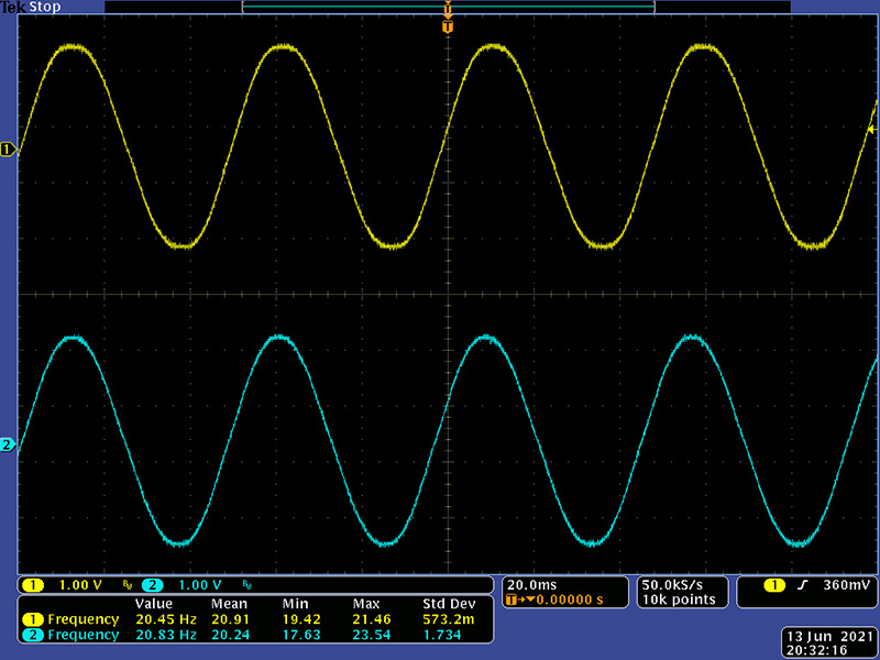
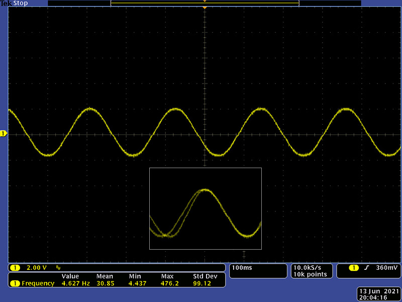
The sine calibrated quite nicely. One of the VCOs couldn't quite reach 5 Hz with the Fine control centered so I added a 1M5 resistor from pin 2 to 4 of IC2 to offset the frequency down a bit.
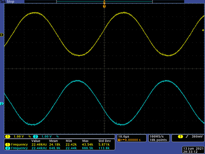
The maximum frequency was a bit over 30 KHz which reflects a 0.4% tuning error over 12.5 octaves. I increased the 100K resistor from the Coarse control to 105K which dropped the maximum frequency to just over 20 KHz. The sine shape and amplitude remain quite good.
I had to tweak R46 for the waveshape control. R46 for the saw is 750K and R46 for the square is 1M. I adjusted the trimmer so there was no visible distortion of the sine wave at waveshape CCW.
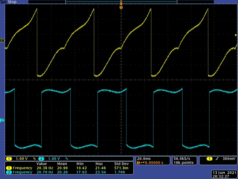
The symmetry is a bit off at the very low frequencies so I added a 20K trimmer between the collectors of Q4 with a 10M resistor from the wiper to ground to trim it. You can see the correction in the insert on the left edge.
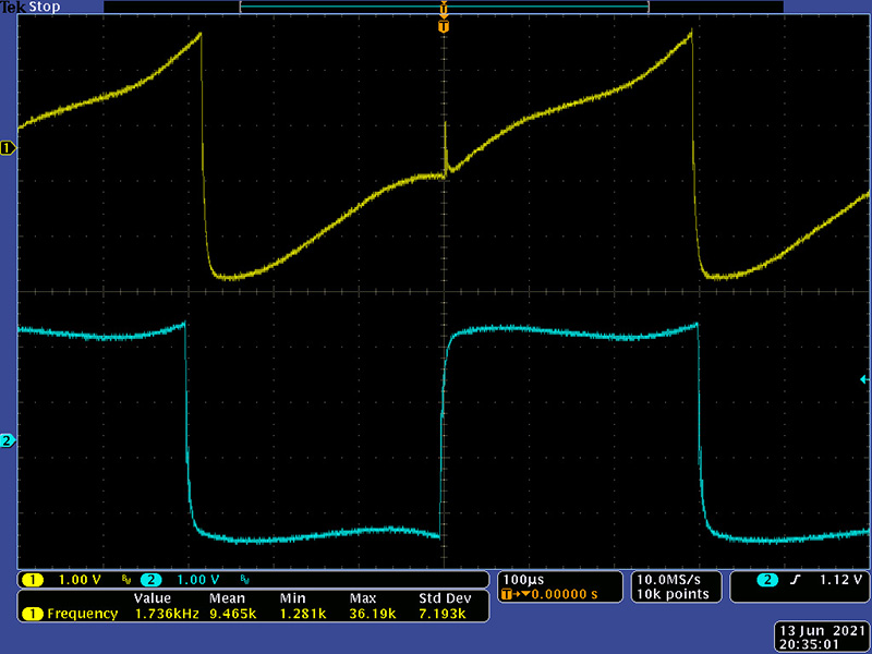
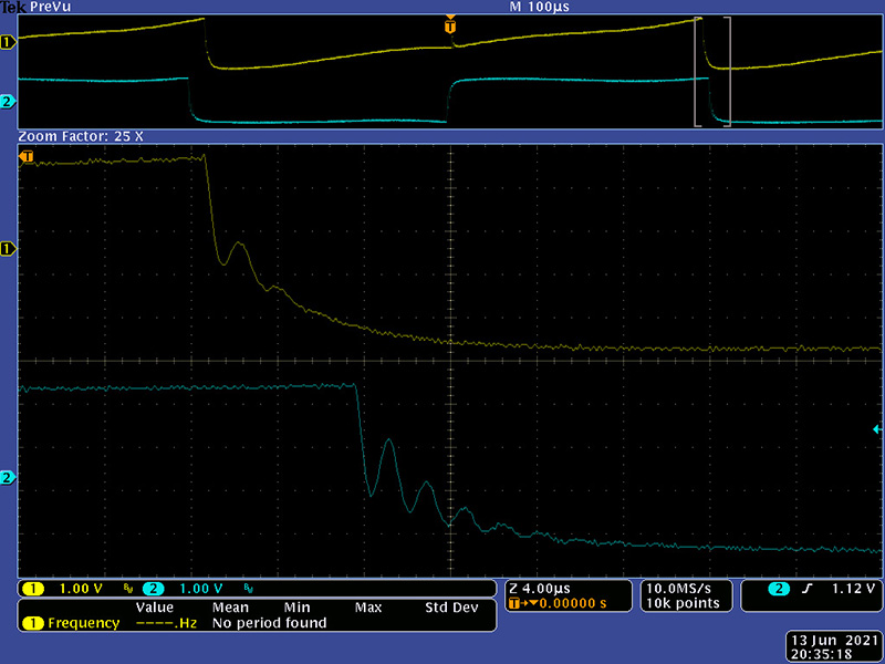
At about 1700 Hz you can start to see increased oscillations at the center of the saw and on the edges of the square waveforms.
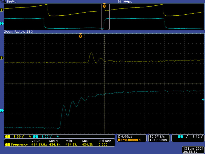
Zooming in you can see the oscillations on both edges of the square and the corresponding saw. This isn't surprising since the comparator is a simple transistor circuit. I decided to leave this since this is likely how these vintage modules operated.
This rear view shows the symmetry trimmers and the 1m5 resistor modifications.
I installed this in my slant cabinet to calibrate it to match my other two 258s. I used my 218 for CV and was able to scale it easily over the 4 octaves of control it provides. Note the unlabeled 56K resistor in the HF trim circuit is not on the PCB so the trim is not as sensitive and ended up with the trimmers set to minimum (e.g. maximum resistance). My other 258s scaled best with this HF trim circuit disabled so the performance of this module showed the same results.