|
285M
Frequency Shifter |
|
I did not built the 285M frequency shifter but did work on and calibrate it.

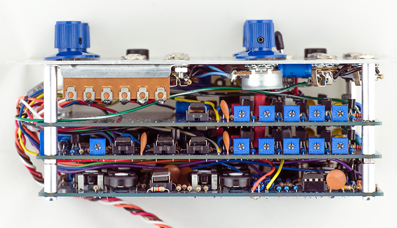
This is a three PCB module. The middle PCB has the filters (right) and the thru-zero reference oscillator (left). The PCB closest to the panel is the same PCB with the reference oscillator parts not installed.
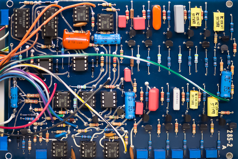
The rear PCB has the three multipliers and associated circuitry.

For operational images of the 285 see my clone 285r Frequency Shifter page.
The trimmers for the phase filters are on the right side of the module. The middle PCB also has the sine shape trimmer.
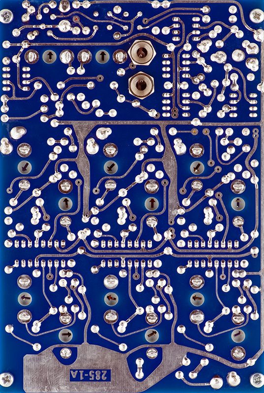
On the rear of the PCB are the trimmers for the multipliers. There are a lot of trimmers on this module but calibration is pretty straightforward.
Calibration
Calibration is not difficult but does require a two channel oscilloscope.
Reference Oscillator Calibration
These adjustments are all on the middle PCB. Connect your scope input to the sine wave test point wire.
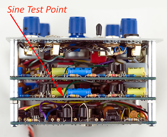
Set the Reference control to some reasonable frequency (100 - 500Hz) and adjust R89 for a nicely shaped sine.

Two additions from the original design are the addition of trimmers for sine symmetry and minimum frequency. On the original, one would pick different value resistors for R* and R+ and connect them to either + or -15V which was a tedious process. The two multi-turn trimmers are mounted on the edge of the PCB for access. This photo shows the orientation of the two trimmers. Set the Reference control fully CW and observe the sine wave. Make sure the sine does not go through zero. This is indicated by an increase in frequency as you continue to decrease the front panel control to minimum. If so, you need to increase the minimum frequency so it doesn't pass through zero.
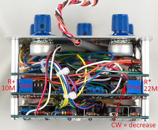
The symmetry will sometimes degrade at very low frequencies. I typically trim the symmetry at a higher frequency, say 10 Hz, and check it both higher and lower and trim to the best compromise. Then I trim the minimum frequency as low as possible while maintaining good symmetry. I was able to adjust this minimum frequency to 1 Hz with good symmetry. Make sure you do not trim the frequency through zero.
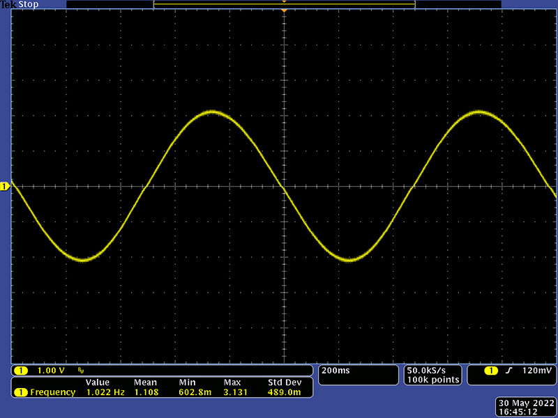
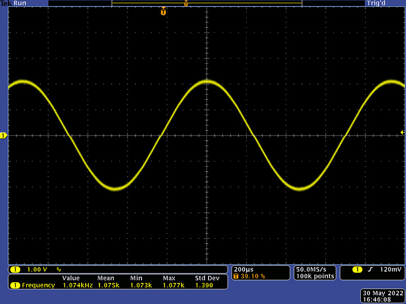
The maximum frequency is just over 1KHz.
The remainder of these calibration instructions and images are from my work on an original 285 as they are the same.
Filter Calibration
There are two sets of filters that need to be calibrated. You will need to connect your scope probes to capacitors on the component side of the rear PCB. Note that on the schematic these capacitors are 56 µF which would be 47 µF today. I don't know what value was used originally. The capacitors are there to block any DC component to the multipliers and 4.7 µF sets a rolloff that is a bit high. I would use 47 µF since capacitors today are small enough to fit the footprint and they lower the rolloff frequency.
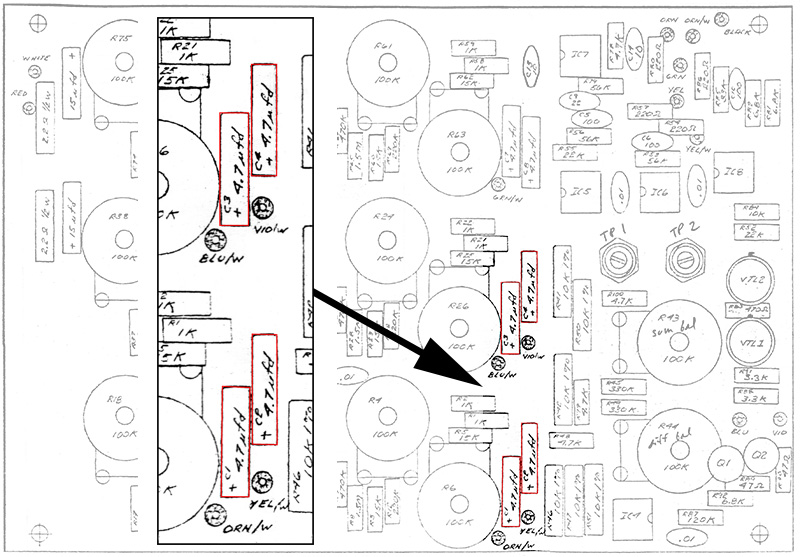
Plug an external sine oscillator into Signal with a +/2V amplitude. Set Reference to Ext (up). Connect a dual channel scope probe 1 to the + side of C2 on the rear PCB. Connect probe 2 to the + side of C3. Make these adjustments on the front (panel) board.
Set the external oscillator to 11 KHz and adjust R55 for a 90 degree phase shift between the two sine waves.
Set the external oscillator to 1100
Hz and adjust R50 for a 90 degree phase shift between the two sine waves.
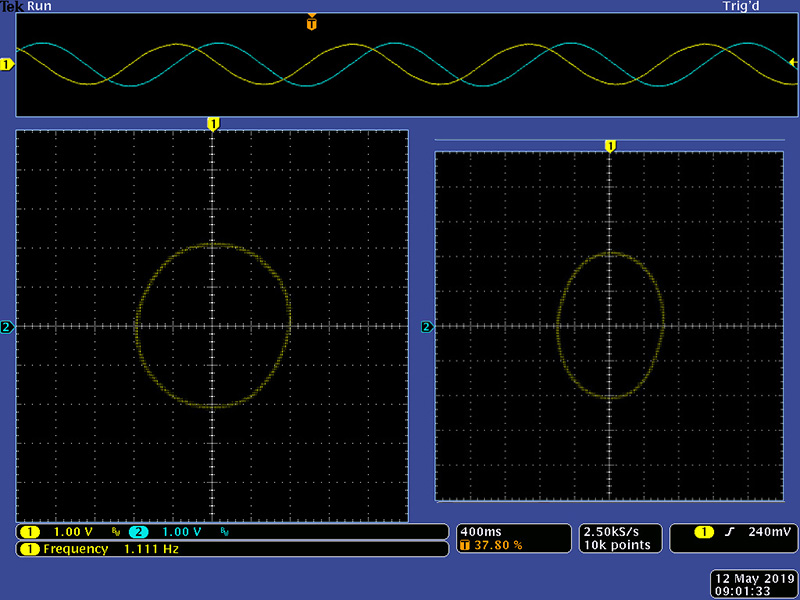
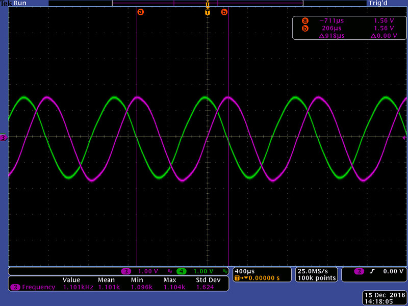
This image shows the two waveforms. I used the cursor as a visual aid
to adjust the green waveform zero crossing to the magenta waveform peak.
An alternate calibration method and more useful for the lower frequencies is to display the two signals in XY mode. A 90 degree phase shift will form a circle if the two signals are equal (left image). They likely differ in amplitude so will display an ellipse but adjust until the ellipse is symmetrical about the X and Y axis (right image).
Set the external oscillator to 110 Hz and adjust R45 for a 90 degree phase shift between the two sine waves.
Set the external oscillator to 11 Hz and adjust R40 for a 90 degree phase shift between the two sine waves.
Set the external oscillator to 1.1
Hz and adjust R35 for a 90 degree phase shift between the two sine waves.
Plug an external sine oscillator into Ref. Connect probe 1 to the + side of C4 on the rear PCB. Connect probe 2 to the + side of C1. Make these adjustments on the middle board.
Set the external oscillator to 11 KHz and adjust R55 for a 90 degree phase shift between the two sine waves.
Set the external oscillator to 1100 Hz and adjust R50 for a 90 degree phase shift between the two sine waves.
Set the external oscillator to 110 Hz and adjust R45 for a 90 degree phase shift between the two sine waves.
Set the external oscillator to 11 Hz and adjust R40 for a 90 degree phase shift between the two sine waves.
Set the external oscillator to 1.1 Hz and adjust R35 for a 90 degree phase shift between the two sine waves.
Frequency Shifter Multiplier Calibration
Make these adjustments on the rear PCB. Plug an external sine oscillator into Signal with a +/2V amplitude. Set Reference to Ext (up). Connect a dual channel scope probe 1 to TP1 and probe 2 to TP2. Set these channels to AC coupled and a low setting in the 10mv - 50mV range.
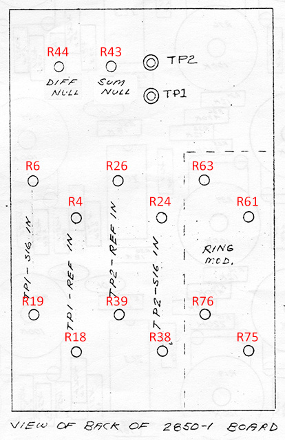
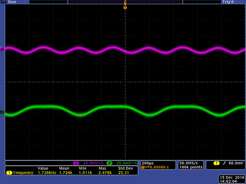
Adjust R19 for a minimum waveform on TP1. Once this is set to minimum, then adjust R6 to further minimize it. This scope image shows the initial waveforms on TP1 and TP2.
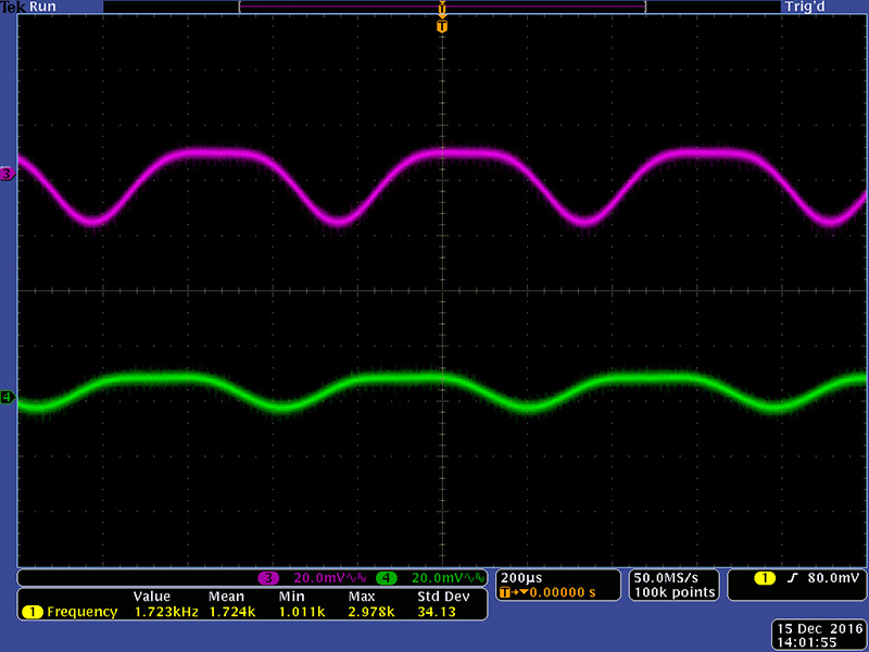
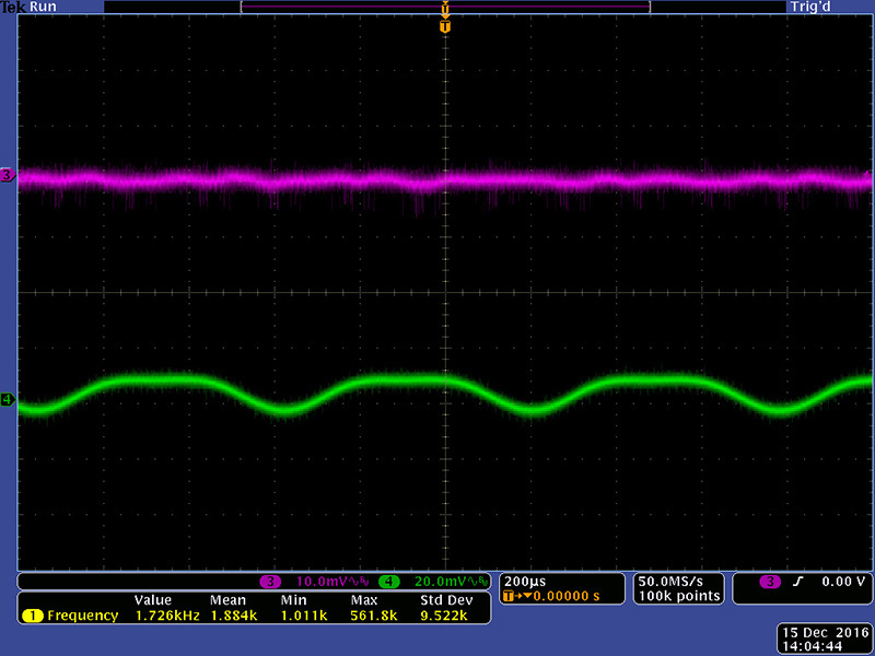
This scope image shows the result of minimizing TP1 with R19.
This scope image shows the result of minimizing TP1 with R6. Note I have increased the sensitivity from 20mV to 10mV.
Adjust R38 for a minimum waveform on TP2. Once this is set to minimum, then adjust R24 to further minimize it.
Remove the external sine oscillator and plug it into Ref.
Adjust R18 for a minimum waveform on TP1. Once this is set to minimum, then adjust R4 to further minimize it.
Adjust R39 for a minimum waveform on TP2. Once this is set to minimum, then adjust R26 to further minimize it.
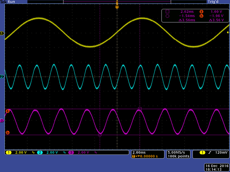
The Sum Null R43 and the Diff Null R44 set the balance between the two multipliers. They have very minor adjustments so you can always just center them. Make these adjustments on the rear PCB. Plug an external sine oscillator into Signal with a +/2V amplitude and set Reference to Int. Adjust the display until you get a stable Sum (cyan) and Difference (magenta) output. I used my cursors to highlight the peaks differ in amplitude.
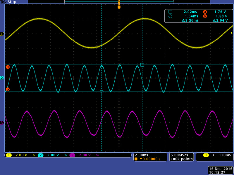
Adjust the Sum Null R43 first until you get the peaks of the Sum Out even.
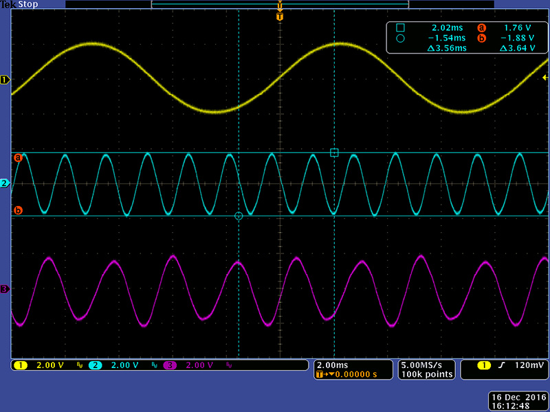
Adjust the Diff Null R44 second until you get the peaks of the Difference Out even. There is some interaction in the trimmers so you may have to go back and iterate to get them even.
Balanced Modulator Multiplier Calibration
Plug an external sine oscillator into Signal with a +/2V amplitude. Connect a scope probe to Ring Out. Set the channel to AC coupled and a low setting in the 10mv - 50mV range. Make these adjustments on the rear PCB.
Adjust R76 for a minimum waveform. Once this is set to minimum, then adjust R63 to further minimize it.
Remove the external sine oscillator and plug it into Ref.
Adjust R75 for a minimum waveform. Once this is set to minimum, then adjust R61 to further minimize it.