|
µA726
Replacer |
|
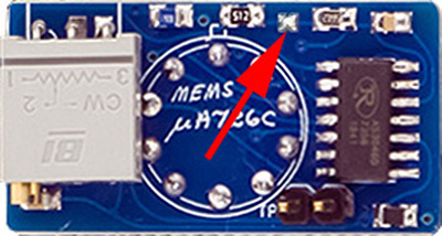
Several of Don's VCO designs use the µA726 temperature controlled exponential pair. These are now rare and hard to find. MEMS designed a replacer PCB which works in all of their modules. It consists of a AS3046 transistor array with transistors used for the exponential pair, chip temperature sensor, and heater.

Here are a pair of them installed on a 258MC.

This replacer does need to be calibrated. These are the instructions I wrote for calibration.
µA726 Replacer Calibration
The µA726 replacer calibration can be done assembled on the bench before installation into the module, or after being installed on the PCB. It requires +15V and Ground, and a DMM and some type of temperature measuring device for calibration. The 258A design does not ground one base of the expo pair so pin 6 is used as a ground to make the adapter universal (the heater resistor on the main PCB is replaced with a 0R or wire). The adapter wires to the PCB with pins 1, 2, 3, 4, 6, 8, 9, and 10. The adapter uses no -15V so pin 5 is unused and pin 7 is a no-connect.
If you calibrate the µA726 adapter on the main PCB, you have to separate it from the panel PCB to access it and solder the jumper. While the PCB allows the trimmers to be soldered vertically, and there is room between the PCBs, there are a lot of wires in this area so it is better to mount them folded over the LM723 as shown here. You can solder short wires or test points to the TP pads to connect to your DMM.
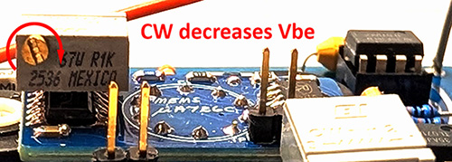
When calibrating the temperature, the AS3046 heats up quickly which changes the Vbe so it makes it challenging to figure out which way to adjust the trimmer. If you mount the trimmers with the screw terminal as indicated by the silk screen, CW rotation decreases Vbe so increases temperature as shown by the arrow above. It's probably best to adjust this trimmer full CCW before you start. That way you can increase the temperature by a CW rotation and measure the effect quickly.
µA726 Replacer Calibration Instructions Do not power on the adapter. Start by measuring the stabilize case temperature of the AS3046 transistor array or the room temperature in °C. (55°C - this measured temperature in °C) is ΔT in the equation below. Attach your DMM to the two test points and ignore the sign. Turn on the adapter and quickly measure the voltage. Turn the power off to not self-heat the AS3046. Move your DMM to the two test points on the second adapter and repeat. These two voltage readings correspond to the transistor characteristics at the measured °C and will be Vbe(cold) in these equations. I chose 55°C for Vbe(op). Subtract the measured case temperature in °C from 55°C to determine the temperature rise ΔT to the desired operating junction temperature of 55°C. Determine each of the desired operating Vbe(op) by the following formula: Vbe(op) = Vbe(cold) - ( 0.002 x ΔT) For the right side µA726 adapter, my Vbe(cold) was -0.6945V (so 0.6945V) with a case temperature of 18.6°C. Therefore, my operating Vbe is: Vbe(op) = 0.6945 - ( 0.002 x (55 - 18.6)) = 0.6217V For the left side µA726 adapter, my Vbe(cold) = 0.7001V with a case temperature of 18.6°C. Therefore, my operating Vbe is: Vbe(op) = 0.7001 - ( 0.002 x (55 - 18.6)) = 0.6273V Start by turning the adjustment screws fully CCW as described above. Solder bridge the jumpers on one of the adapters. I would recommend you calibrate one at a time (i.e. leave the other adapter jumper unsoldered) because you can easily overheat the AS3046.
Connect your DMM to the test points and ignore the DMM sign. Turn on the module and slowly turn the adjustment screw CW until the desired Vbe(op) is reached. There is a slight lag for the voltage to stabilize. Now solder the jumper on the other adapter and repeat. Your adapters are now calibrated for ~55°C. |
µA726 Replacer calibration instructions PDF