|
Moog System 55 Console Panels |
|
Moog modular synthesizers had a number of "half panels" or console panels that bussed controller signals to various modules and provided some additional functionality such as signal mixers, multiples, and routing. The Console Panels are hard wired and mounted on hinges to the bottom of the cabinet.
Console Panel 2
Console Panel 2 has passive low pass and high pass filters, multiples, and pitch and trigger outputs from the three controller jacks in the rear.

Here is the view of the CP2 panel open. The serial number labels are simply attached to the inside bottom of the cabinet behind the console panels.
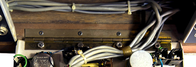
Here is the CP2 rear.
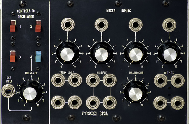
Console Panel 3A
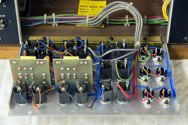
There are three Console Panel 3A in the Moog System 55. The CP3A has switches for routing four controller CV signals, a four input mixer, multiples, and trunk jacks. The switches are rear illuminated to indicate which controllers are patched in. The mixer provides non-inverted and inverted outputs with a master gain control.
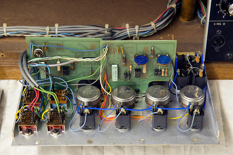
Here is the view of the CP3A panel open. These late model CP3A panels use op-amps instead of transistors, runs off +/-15V for increased headroom, and uses two of the same PCB but populated differently.
The PCB on the right is the 4 channel mixer and has a gain of 2X. The trimmers are for offset voltage and the one towards the middle of the PCB is for the inverting output and must be adjusted first. The one towards the edge of the PCB is for the non-inverting output and must be adjusted second. This does have a published schematic but I have added the DIP pin numbers and corrected a few omissions.
| IMPORTANT The PCB on the left is for CV mixing and it has a scale trimmer on it. I have never found a schematic of this PCB although I did trace it out and create one below. A resistor network is used which has very tolerance between resistors. This trimmer must be set to unity gain BEFORE scaling any of the oscillators. Assuming the resistors are matched, the trimmer will adjust the gain from 1.0X to 1.08X. Two of the three CP3A would adjust to 1.0X while the third adjusted to just slightly more than 1X. A 499K resistor could be added in parallel across the DIP resistor pack from pin 2 to 15. This would reduce R6 slightly and scale trimmer would adjust the gain from 0.96 to 1.04X. |
I adjusted the trimmer by setting the voltage between the input and output to 0V. The CV input is on the center pin on the right side of the upper left CV switch (for the keyboard). The CV output is the wire jumper in the lower right corner of the PCB. I also replaced the open frame trimmer which seemed to have a high failure rate with higher quality Bourns trimmer.
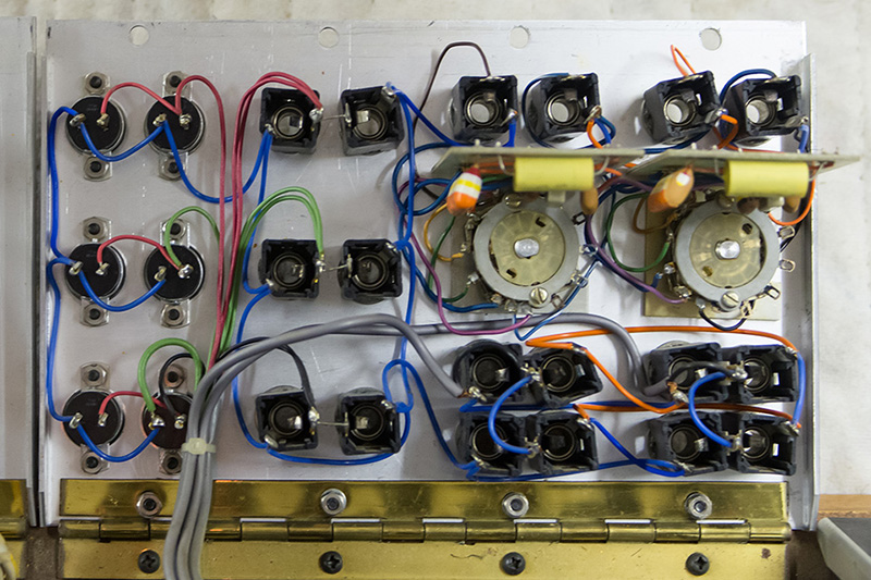
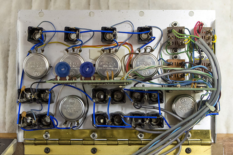
Here is the CP3A rear.
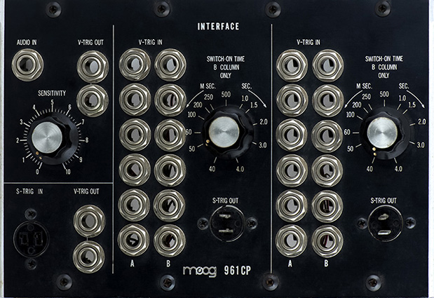
Console Panel 961CP
The 961 Sequencer Interface module is reformatted into a CP panel. More photos are on the 961CP page.
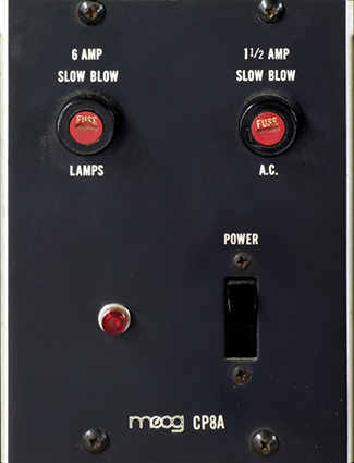
Console Panel 8A
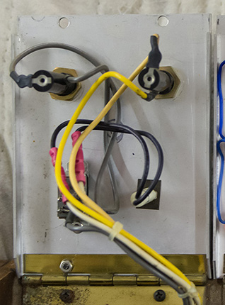
The power switch, power light, and fuses are mounted on a smaller console panel and are well labeled.
The AC wiring is considerably cleaned up and insulated from the previous CP8 panel.
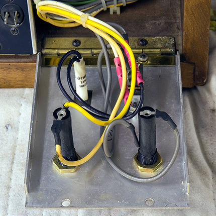
Here is the CP8A rear.