 |
211 Power Supply |
|
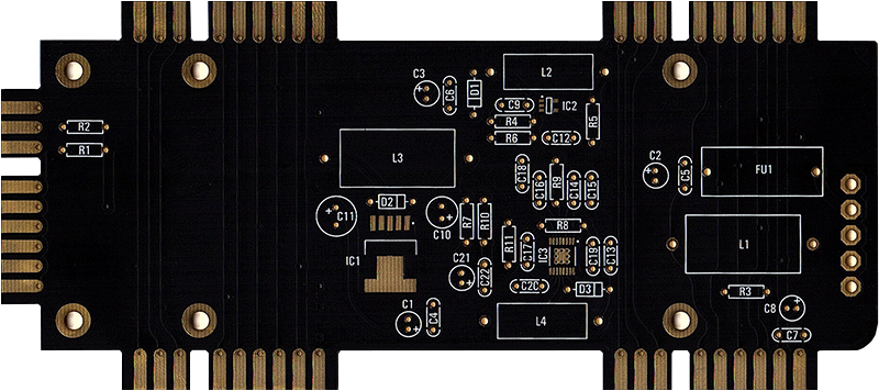
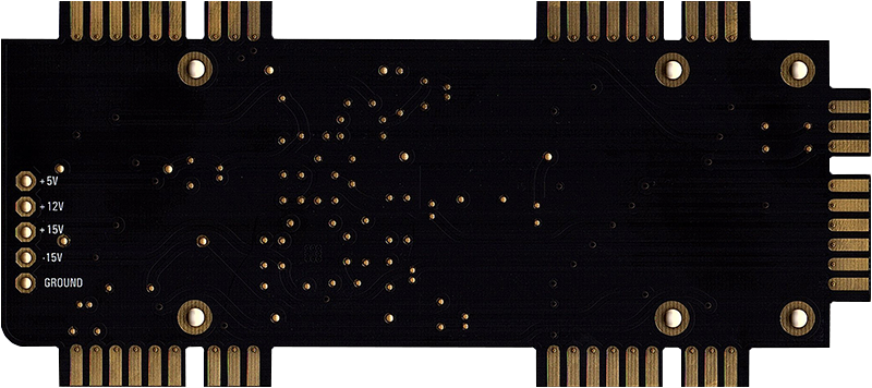
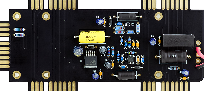
I built a 211 Power Supply for a customer. The PCB build is pretty straightforward. The +12V is supplied by the regulated external power supply and the +/-15V and +5V supplies are generated from the +12V.
IC1 (LM2575) and L3 are used for the +5V supply.
IC2 (LM27313) and L2 are used for the +15V supply.
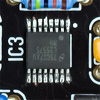
IC3 (LM25575) and L4 are used for the -15V supply.


The ground planes do soak a lot of heat when soldering. The yellow L3 inductor is a replacement for the Bourns 330 ÁH since Mouser was out of stock. I used an API Delevan (Mouser 807-4590R-334K) inductor as a replacement.

The fine pitch IC3 takes a steady hand to solder. This is about at my limits for hand soldering.

There are several regulated external power supplies like the Cincon TRH50A120 to operate the 211 power supply. I prefer to use a Meanwell GSM60A12-P1J 12 volt 5 amp Medical Adapter (Mouser 709-GSM60A12-P1J). The AC mains earth ground is connected to the DC negative supply so the panels of the modules will connect to earth ground. Many other DC adapters, like the Cincon, are isolated so grounding is dependent upon external equipment being connected to the 208. The red arrow on the GSM60A12-P1J data sheet illustration signifies this connection to earth ground.

The external power supply simply connects to the +12V and Ground pads near the fuse.