|
25S Analogue
Waveform |
|
I have not built a 25S but I have repaired and calibrated a number of them.
Modifications
The FM modulation appears to operate more as a square wave on any of the three MO settings. The MO buffer has too much gain so the waveforms clip. Change R245 on PCB3 to 1K so it is the same value as R248. The FM circuit is AC coupled, but it is AC coupled before the buffer. The output of IC39 pin 7 has to match the DC level on the expo current sink, otherwise there will be a frequency shift. There isn't enough range to typically get to this DC level so change R244 to 10K. Note that if he put the coupling capacitor after the buffer there wouldn't be this issue.
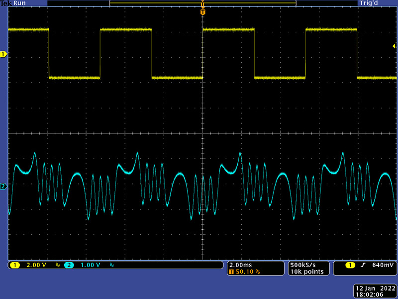
Verify the modulation follows the MO waveshapes. Note the FM modulation is linear, not exponential, so the modulation index does not result in a significantly wide range. Note also that the MO is AC coupled to the linear FM so on low frequencies the MO waveshape is distorted as one would expect.
The pitch modulation suffers from a couple of different issues. It needs to be AC coupled through C100 and that gives it a time constant. When modulating with the square wave, one just gets an impulse response. The triangle and ramp isn't much better. You can increase R248 to 10K and increase C100 to 100 µF. That gives a time constant of 1S. Leave R244 as 10K and replace R245 with a 50K trimmer. You can now set the depth of the FM modulation with the trimmer. Too much gain and modulating with a square wave drives the lower frequency to near 0Hz so it sound more like AM modulation. I adjusted the trimmer to have a nice range for the three wave shapes. The gain affects the offset, so when complete, adjust the offset so there is no frequency change when selecting pitch. When you turn down the index control, the 1S time constant can be heard as the waveform drifts back to the root.
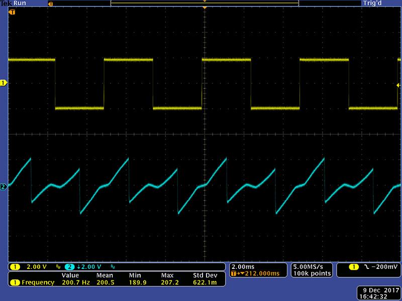
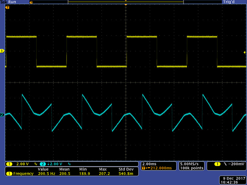
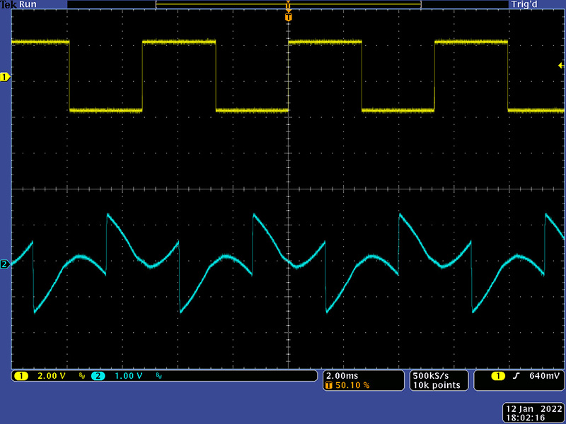
The pitch modulation is linear, so the upper and lower frequencies should be a constant delta from the root. To verify this, I set the CO to 250 Hz, or a 4 mS period.
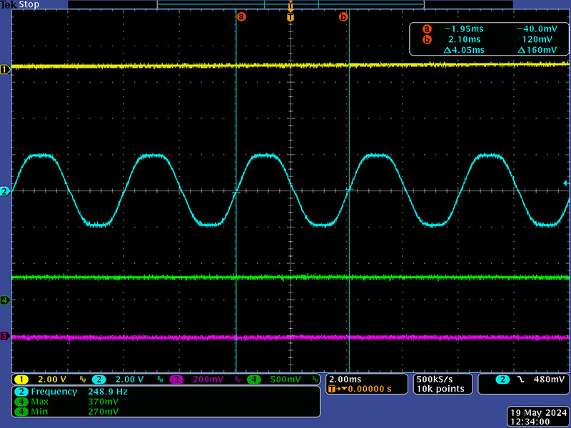
I then pitch modulated with a triangle and read the period at the upper and lower frequency limits. The upper frequency measured 3.4 mS which corresponds to 300 Hz.
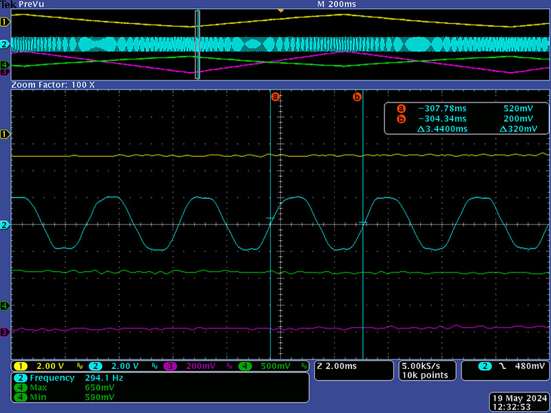
The lower frequency measured 5 mS which corresponds to 200 Hz. Thus the pitch modulation is linear at +/-50 Hz.
None of the 3.5mm jacks have a ground wire so the front panel and 3.5mm jacks have to be grounded through the boat. The CCW terminal of either FM control at the bottom is ground so I ran a wire from these to the 3.5mm FM jacks. The grounds should be routed to all 3.5mm jacks so grounding does not rely upon the anodized panel.
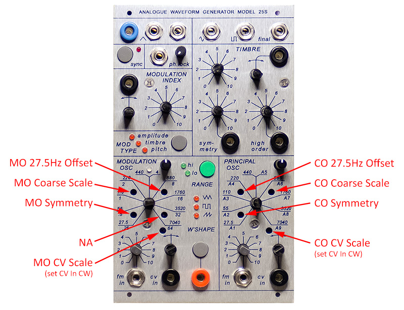
Calibration
Monitor MO output
Set MO Coarse control to CCW, MO fine control to MID
Set Range to Hi
Adjust MO Symmetry trim for best triangle symmetry (adjust first as it affects
the frequency)
Adjust MO 27.5 Hz Offset trim to low frequency desired (27.5 Hz)
Select Lo Range and check symmetry; iterate for best symmetry
Set MO Coarse control to CW, leave MO fine control at MID
Set Range to Hi
Adjust MO Coarse Scale to highest frequency desired.
Set MO Coarse to some mid frequency
Adjust MO CV Scale for proper tuning
Monitor CO Sine output
Adjust rear sine trim for best sine shape
Set CO Coarse control to CCW, MO fine control to MID
Set Modulation Type to none and Index to CCW
Adjust CO Symmetry trim for best sine symmetry (adjust first as it affects the
frequency)
Adjust CO 27.5 Hz Offset trim to low frequency desired (27.5 Hz)
Recheck rear sine trim for best shape
Set CO Coarse control to CW, leave CO fine control at MID
Adjust CO Coarse Scale to highest frequency desired.
Set CO Coarse to some mid frequency
Adjust CO CV Scale for proper tuning
Monitor Final output
Set Timbre, Symmetry, High to CW
Adjust Timbre trim until waveform just starts to change from sine, then back it
off just a bit
Set Mod Type to Pitch
Adjust rear FM Offset trim so there is no change in frequency. You will
need to cycle through the Mod Type several times to get this set correctly.
Calibration is complete
Timbre
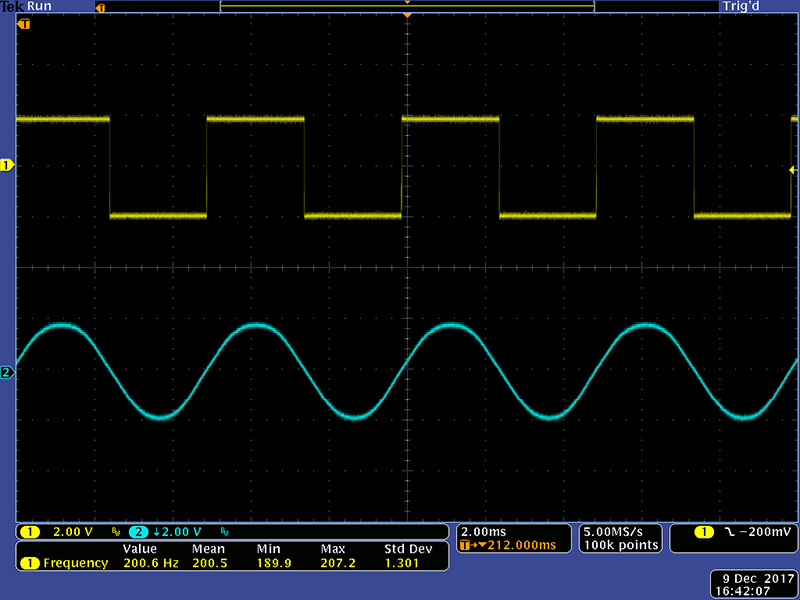
I've repaired and calibrated a number of 25S modules. The timbre circuit seems to have a lot of variation which may be related to the tolerances of later vactrols and the LS3958 dual JFET. I decided to put these images of the final waveform of a typical 25S timbre with various settings of the three controls. First is with all three controls set to CCW so we just have a sine wave output.
Turning the Symmetry control CW has no affect but turning the Order control CW increases the amplitude of the sine slightly.

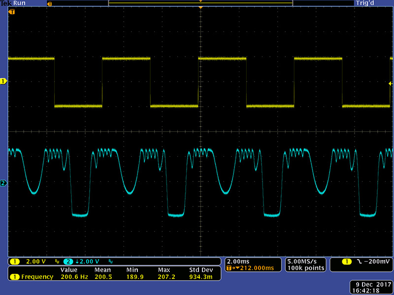
Turning the Timbre control CW with the Symmetry and Order controls CCW produces a lot of folding with square corners. In my opinion, this is not a good sounding timbre. See Epilog below for modifications.
Leaving Timbre at CW and turning the Symmetry control CW makes a minor change.
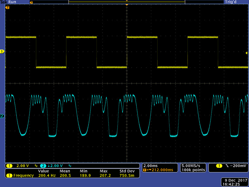
Leaving Timbre at CW and Symmetry at CCW and turning the Order control CW creates a ramp-like waveform that is a folded sine with a half inversion.
Leaving Timbre and Order at CW and turning the Symmetry control CW creates a folded sine.
V2
I have not seen a V2 but have corresponded with customers trying to help. V2 appears to incorporate all the changes from the V1 build notes. An additional trimmer TR11 was added on PCB3 for timbre range. It adds a negative offset voltage to the wiper of TR9 so it will offset the control voltage to the timbre circuit. Without documentation, it appears these are the changes.
PCB1: Add R63 2K2
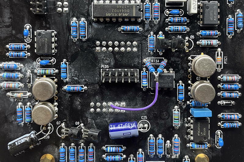
PCB2: Add R134 11K, and R135 10K.
PCB3: You still need to change the value of R245 to 1K so it is the same value as R248. Add TR11, value unknown, but it is a series resistor between -15V and the wiper of TR9. Try 100K but note that if TR11 is set to the minimum, and TR9 is set to the minimum, you ground the -15V supply through both trimmers and burn them out.
I believe TR9 now sets the range and TR11 adjusts the offset, but they will interact with each other. I haven't seen an actual V2 PCB to verify how to set calibrate these trimmers and it isn't obvious from the circuit to determine what procedure to adjust them. I would adjust TR11 to maximum value. (you’ll have to measure between the pins to determine this). Then adjust TR9 to the eliminate folding with timbre off. Then set the timbre to maximum. See if TR11 will back off the maximum. Then check with no timbre and tweak TR9 as necessary.
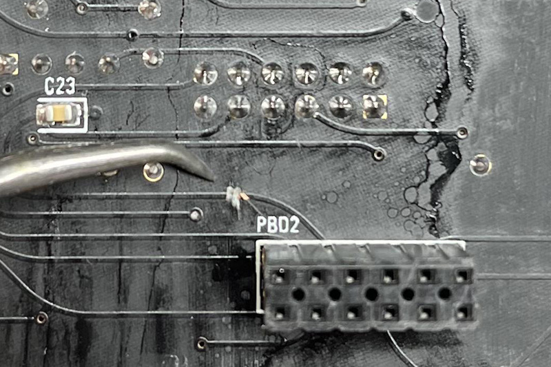
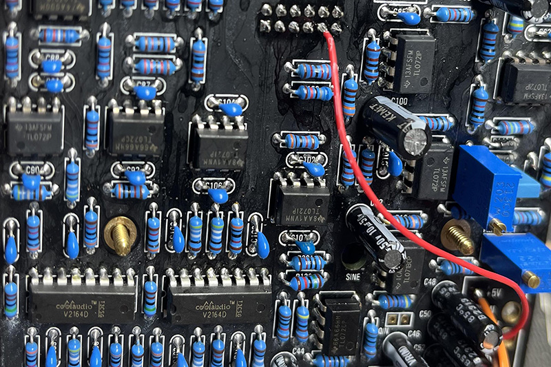
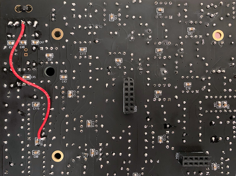
I've seen a number of black/gold PCBs with open runs and vias and some with shorted runs. I've helped an individual who had issues with an open run on +15V on PCB3. My initial assumption was this was just another case of a bad etch. I've been notified by other individuals that their PCB3 has the same problem. This issue is detailed in the Muffwiggler thread ANALOGUE WAVEFORM GENERATOR MODEL 25S. I didn't keep a record of the fix that I helped with but this photo is from that Muffwiggler thread showing the mod.
Epilog
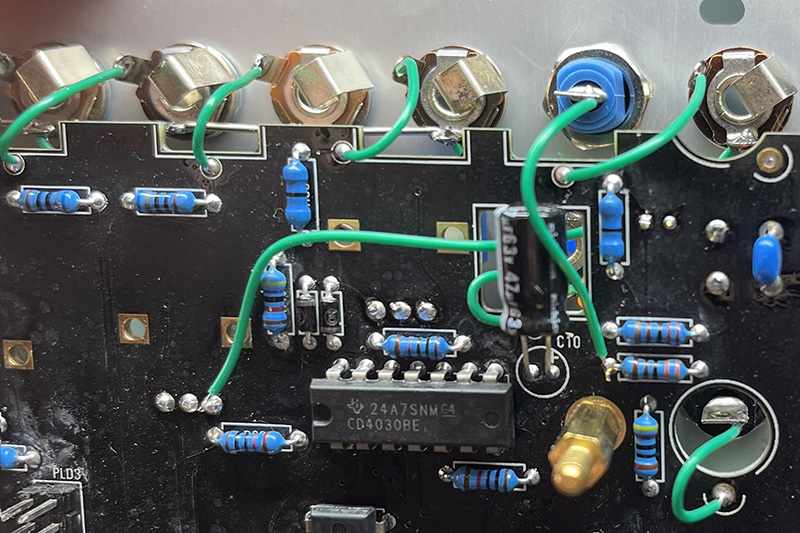
I have been sent a number of 25S modules to work on timbre. Timbre works on using multiple CA3140 cells to fold. They are controlled by the amplitude of the sine wave input which is increased by a VCA comprised of Q10 and IC24. One can pick multiple JFETs but I simply adjust the feedback resistor to set the maximum gain.
Remove TR11 and leave it out.
Fold the wiper over to one side to make an adjustable resistor. I set it initially to 33K and replace R188. You'll have to spread the legs a bit to fit. Then with the frequency around 200 - 400 Hz I set timbre control on minimum and adjust the sine and timbre trimmers to get a good formed sine with no folding.
Set the timbre control on maximum and adjust this new R188 trimmer until you get nice folding with no square edges. I typically find the value down somewhere around 15K but I adjust by ear and scope.
Adjust the frequency and check the "smoothness" of the timbre control. Sometimes there are "clicks" which you can adjust out by lowering the maximum timbre range (R188).
Change R224 from 33K to 22K to decrease the symmetry and order levels so they don't change significantly.
These are the waveforms I got when using this modification. Here is a nicely formed sine wave.
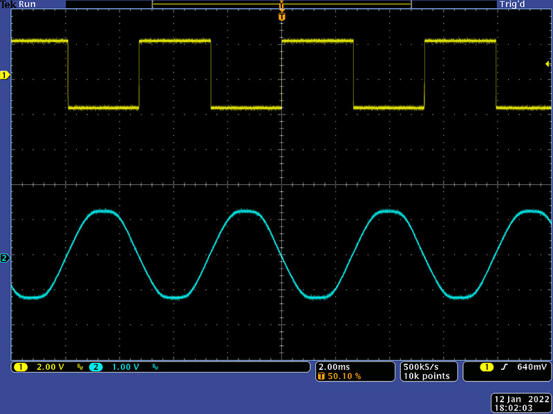
Timbre at maximum has a nice number of folds and no square edges.
Symmetry and Order are reasonable amplitudes.

Epilog2
The MO outputs are all low based on the design. On the 259, the MO CV output (banana) is a 0 to 10V output. I made these modifications to increase the amplitude of all of the levels more in line with the 259.
PCB1
Change R38 from 3K3 to 1K
Remove R40 20K and R63 10K (present on V2 only)
Change R39 from 680R to 2K
Add a 2K to ground at the signal out jack (wire between bottom pad R40 to top pad R39)PCB2
Parallel R81 with 330K or replace with 69K8K to shift saw more positive
Change R89 2K49 to 0R/link
The resultant output levels are ~9.5V for the unipolar CV, and +/-2V for the triangle and output.
Epilog3
An associate sent me these additional modifications he made as a further extension of Epilog2.
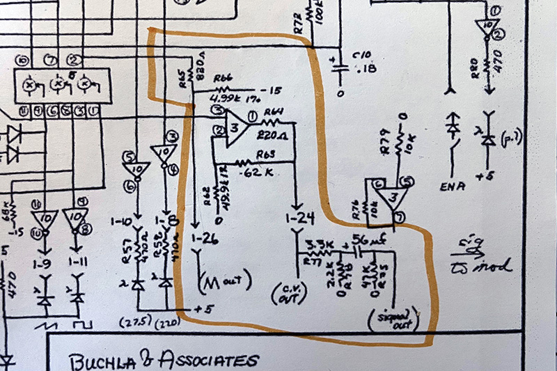
MO CV Out: This is tapped after the voltage divider formed by R38 and R63 (R's 77 and 78 in the original 259 schematic). This is easy enough to address by wiring the CV out directly to the left-most lead of R38 (when viewed from the component side of the board).
Signal Out: He added a 680R resistor (R39) after the 47uF capacitor (C10) and used 20k (R40) where Don had 47k. I replaced R39 w/ a link and R40 changed to the original 47k.
Triangle Out: He added a 680R resistor (R29) where there is no such component in the original.
IC8 (3 in Don's drawing): He changed the gain-setting resistors but the ratio is the same (R's 134 and 135 in Roman's = R's 63 and 62 in Don's). However, the 220R resistor in Don's design (R64) is omitted. Subbing in the original values for R135 and R135 is easy enough but putting the 220R in the feedback loop requires a trace cut and lifting a few resistor leads and flying a wire.