|
205 Dual Matrix Mixer |
|
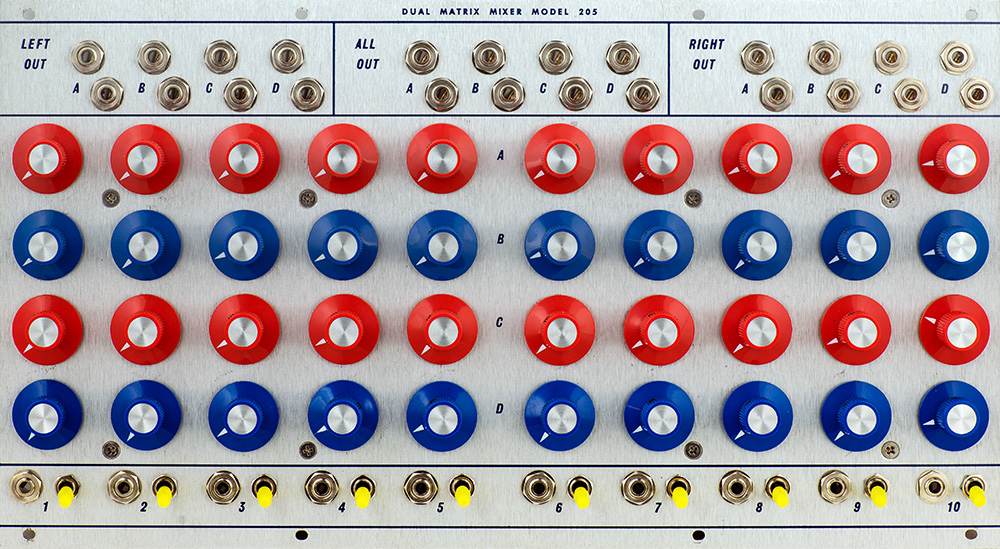
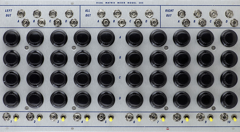
I was sent this 205 to address the bleed issue. The mixer is organized as two independent 5x4 mixers where each of the five inputs can be assigned a level to any of the four outputs. The switch also sends that signal to a pair of left and right monitor outputs. Although they are designated left and right, the monitor channel is mono. A separate set of four outputs in the center combines the left and right outputs.
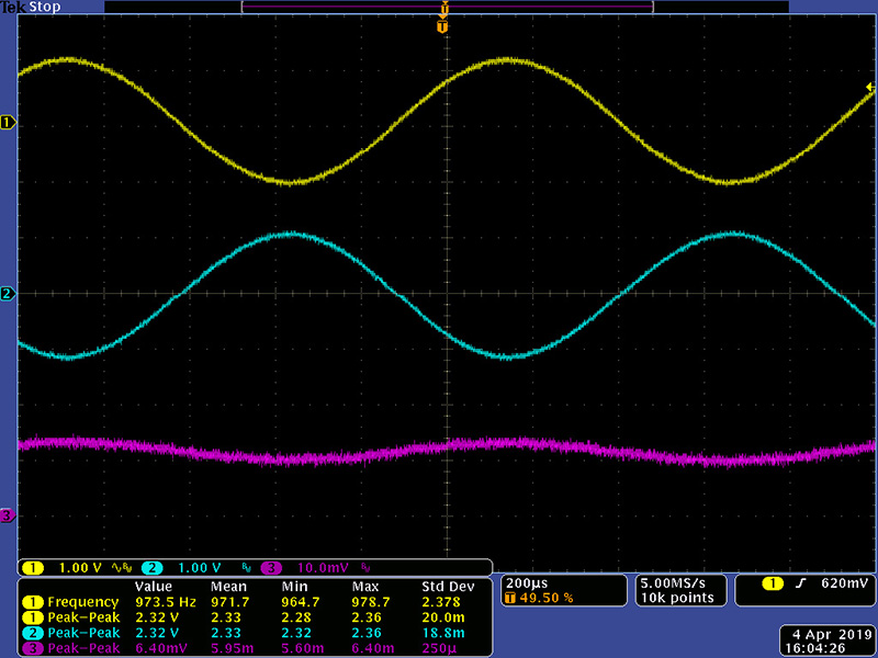
The issue with this mixer was bleed to other channels. I measured the bleed as -51 dB, a low number but still audible. In looking at the schematics, Don used a 2R2 resistor between the CCW terminal of the potentiometers and ground. I have no idea why he did this but this injects some signal into the remaining channels. I replaced R26, the 2R2 resistor, with a jumper and I could no longer measure any bleed. See Epilog at the bottom for more details.
The mixer is inverting and the All Out jacks are again inverted so are in phase with the input. The monitor outputs are also inverted.
The V1.0 BOM specifies a TL071 for IC4 but the part number is for a TL072. The MTA 100 connectors and 15 mm FF standoffs are missing from the BOM.
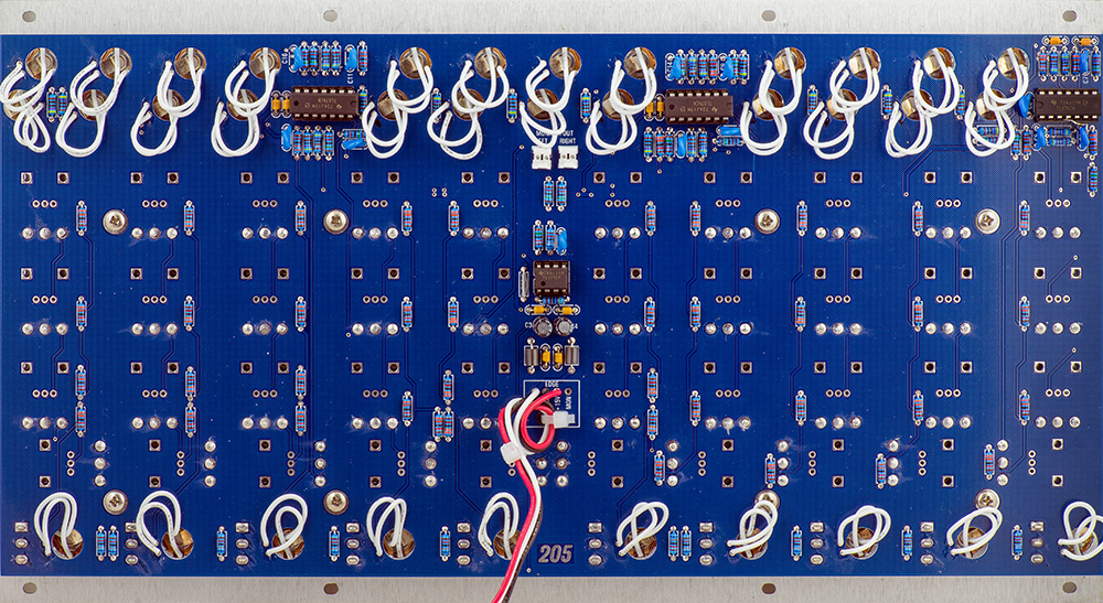
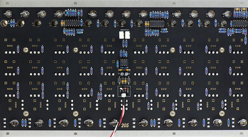
The jumper can be seen in this rear image to the left of IC4 in the center.
205 Build
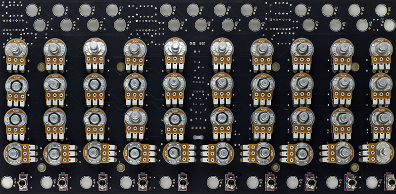
I built this 205 with Davies knobs.
I knew trying to align all these potentiometers through the panel would be a challenge. I chose to bus the grounds for the output jacks and wire the output pairs together to minimize the number of wires to feed through the PCB. I would have liked to bus the grounds on the input jacks but the switches are a bit in the way so I ran individual ground wires.
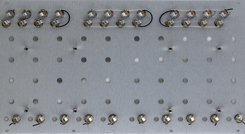
There are a lot of potentiometers to align with the panel. I found this process worked best.
|
The Left and Right Monitor outputs are in parallel with individual 15K series resistors. There is direct monitor output with the power cable pads.
Epilog
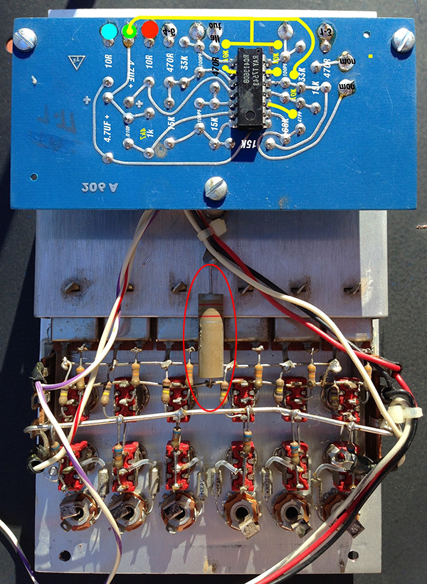
Don used this same 2R2 resistor on the 206 Dual Mixer (circled in red).
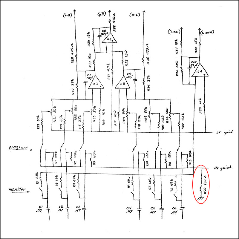
MEMS sent me this photo of the rear of a vintage 206 Dual Mixer. You can clearly see the part in question is a 2.2 µH inductor, not a resistor. This makes more sense and would not cause the bleed issues. I assume Don just carried this schematic error through other similar modules.