 |
280 Quad Envelope Generator |
|
I built a 280 Quad Envelope Generator for a customer. The "sustain" legend indicates the switch so sustain is selected when the switch is up.
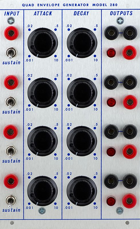
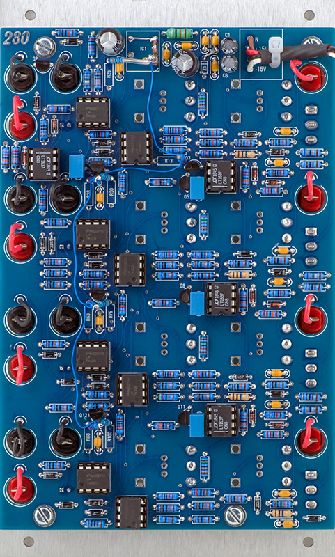
This is a simple single PCB module which uses +/-15V and +24V. I have made modifications to the module to improve operation which eliminates the +24 volts. There are 8 lifted resistors wired to a new +13.8V supply.
Operation
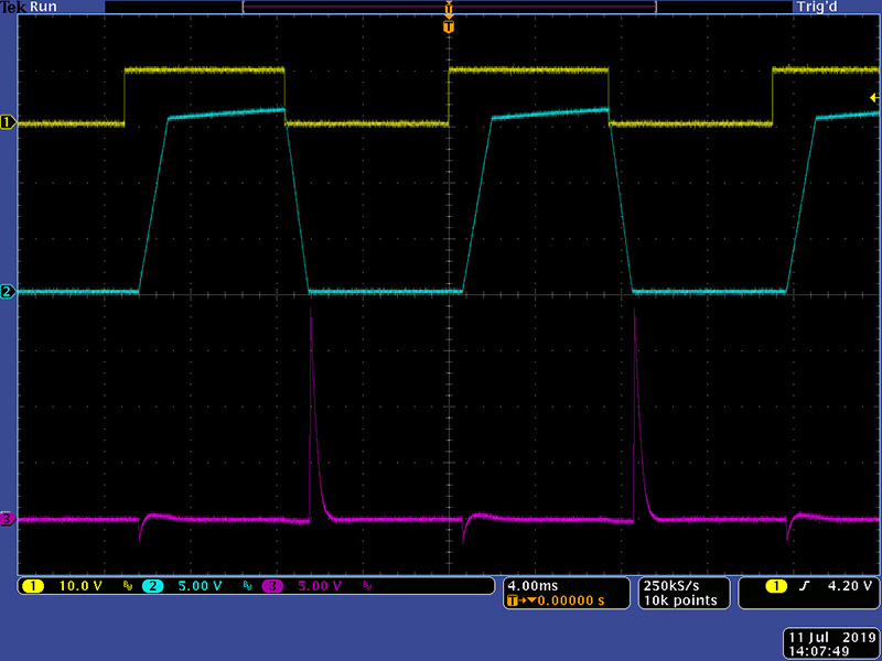
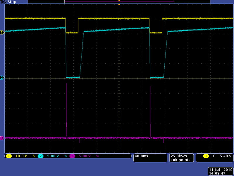
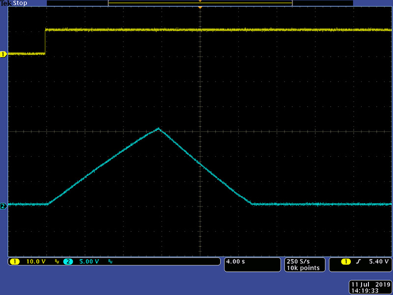
This module has no trimmers. The first thing I noticed on the oscilloscope is the slight ramping upward during the sustain mode. The Pulse output is diode driven so the curve at the trailing end is due to not having a load.
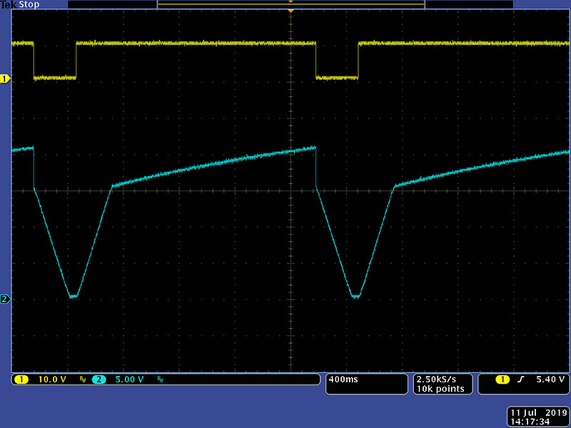
With Attack set to minimum the upward drift becomes quite pronounced.
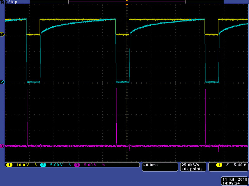
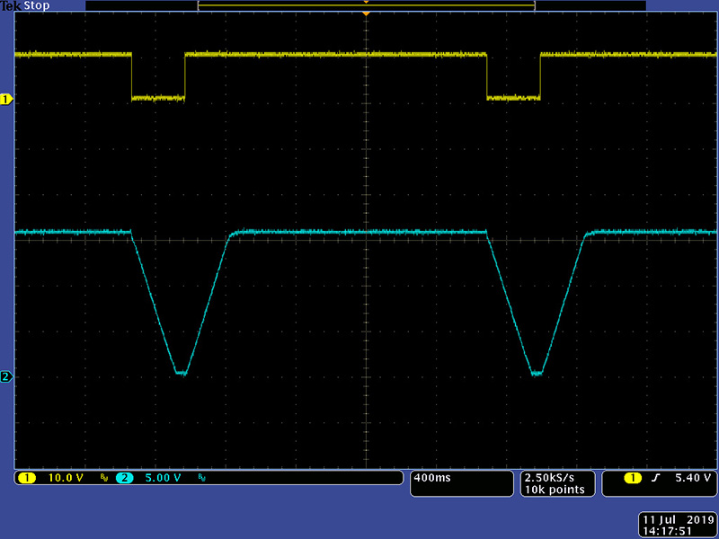
Slightly increasing the Attack improves the upward drift somewhat.
The upward drift continues for a long sustain of 1.5 seconds.
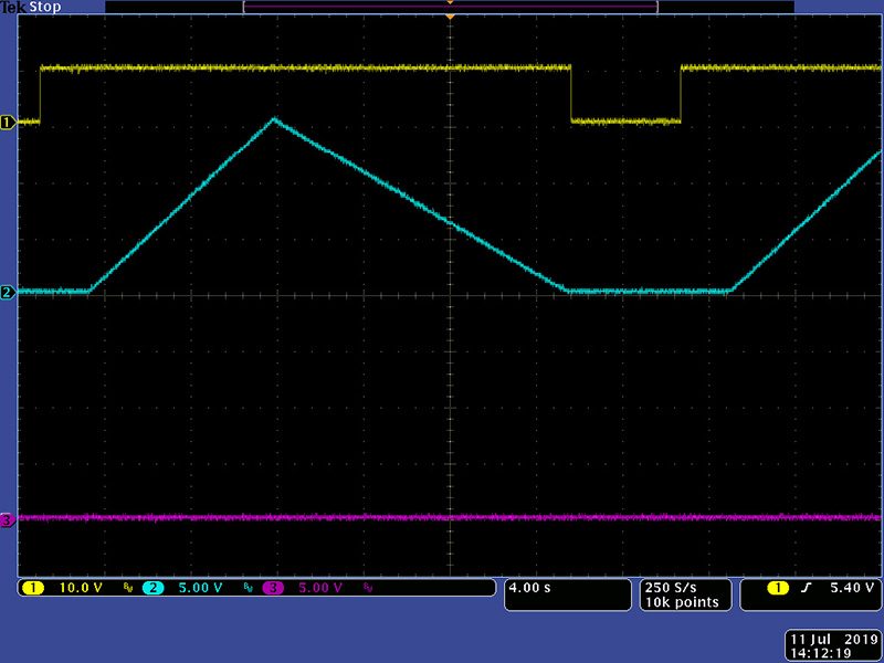
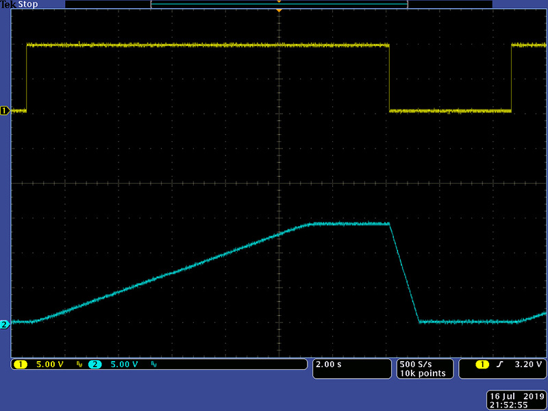
Without sustain, at long attacks there is a noticeable delay between trigger and the Attack. This image shows an Attack-Decay of 22 seconds. The Decay is slightly longer than the Attack but the delay from trigger is nearly 2.5 seconds.
Modifications
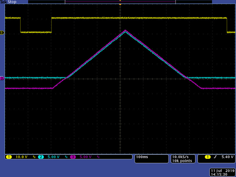
The integrator is powered from +24V/-3V and drifts to both the positive and negative rail. The Attack starts from -3V so the delay is the Attack time until the output diode starts conducting at +0.6V. Magenta is the integrator output and cyan is the Output.
I added a diode between the integrator negative input and output to clamp the integrator low voltage to 0V eliminating the delay.
Likewise I added a clamp diode to prevent the integrator from rising about +15V. The result is a well behaved sustain mode.
Conceptually, while this solution works, the 741 op-amps current limit at 25 mA so it draws a lot of current and more than the +24V DC-DC converter can supply. The circuit is fairly simple and there isn't a lot that can be easily done to limit the integrator between 0V and +15V. I decided the best course would be to replace IC2 with a rail-to-rail LT1637 op-amp and run it on 0 and +15V so the integrator couldn't drift further. The end of attack and the end of decay circuitry required modifications. Q1 detects the end of attack by biasing Q1 on. The base voltage has to be lowered so I created a new Vb supply two diode drops below 15V. Likewise the end of decay used the output of the IC3 comparator and I simply changed the resistance and used the Vb supply. The integrator stops at about 160 mV so I set the pulse threshold at 200 mV. I replaced the +15V to +24V DC-DC converter with a link and removed Z1 and wired the -3V to N to power IC2 from 0 and +15V.
The output is now well behaved with no delay on a long attack and no drift with a long sustain. The customer reports that self-cycling stops when the Decay is rotated near full CW. This might be due to the output pulse not functioning correctly at very long decays. This could occur if the output offset increases at full decay and the 200 mV threshold might be too low. R25, R50, R75, and R100 need to decrease to increase this threshold. This needs further investigation so let me know if you are modifying a 280 Quad Envelope Generator.
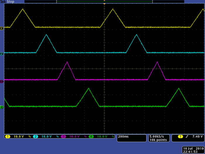
This scope image is simply verifying all the outputs work by connecting the four sections in a ring.
PCB Modifications:
Remove IC1. Jumper the two pads nearest the edge.
Remove Z1. Jumper the pad closest to the edge to the nearby pad of F1
Replace IC2, IC5, IC8, and IC11 with an LT1637 op-amp
Lift the +15V end of R13, R38, R63, and R88
Replace R25, R50, R75, and R100 with 680K. Lift the end that connects to the
output pin 6 of IC4, IC7, IC10, and IC13
Connect two series 1N4148 diodes with the anode to the link at IC
Connect the cathode to a 10K resistor in parallel with a 0.1 µF capacitor to
one of the unused ground pads of IC1
Connect all the lifted resistors to the cathode/10K. You can tilt R38/R50,
R63/R75 and R88/R100 together for stability.
212 Dodeca EG
This same circuitry is used in the 212 Dodeca EG with one additional modification. The output CV is buffered by a TL074 that is powered from +/-15V so the output saturates at 13.5V. The output is then attenuated to 50% so there is no upward drift but the CV output is only 6.75V. This same method could be used as an alternative in the 280 by adding a quad op-amp and a handful of parts but still would have the attack delay. Changing the attenuation to 26% would provide a 10V CV output.
Epilog
I was contacted by an individual who made these modifications and his 280 would not loop on the longest decay settings. Lowering R25, R50, R75, and R100 did not have any affect. We corresponded by email and determined that one channel did cycle and if he moved that 741 to any of the other channel, they would operate correctly. A TL071 did exhibited the same behavior. I was not able to diagnose this by email but he substituted LM301s and all channels operated correctly.