|
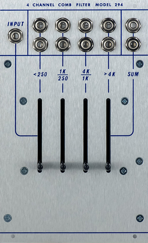
294 Four Channel Comb Filter Module |
|
I built a 294 Four Channel Comb Filter module for someone else. They sent me a mostly complete kit of parts and I assembled and tested the module. Many of the components are sourced through Mouser but specialized parts, panel, and knobs have specific sourcing requirements. This is one of the simplest 200 series modules.
I made a reference diagram from the PCB.
The only components on the front of the PCB are the four sliders. There are metal tabs on the sliders that do touch the PCB so I covered the PCB with tape where there are runs as only the solder mask provides insulation. See the 296 module page for detailed photos of the tabs.
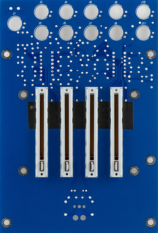
I bused the ground on the 3.5mm jacks and only connected them to the PCB at both ends.
|
294 Modifications (see description under Operation)
Optional modifications
|
Operation
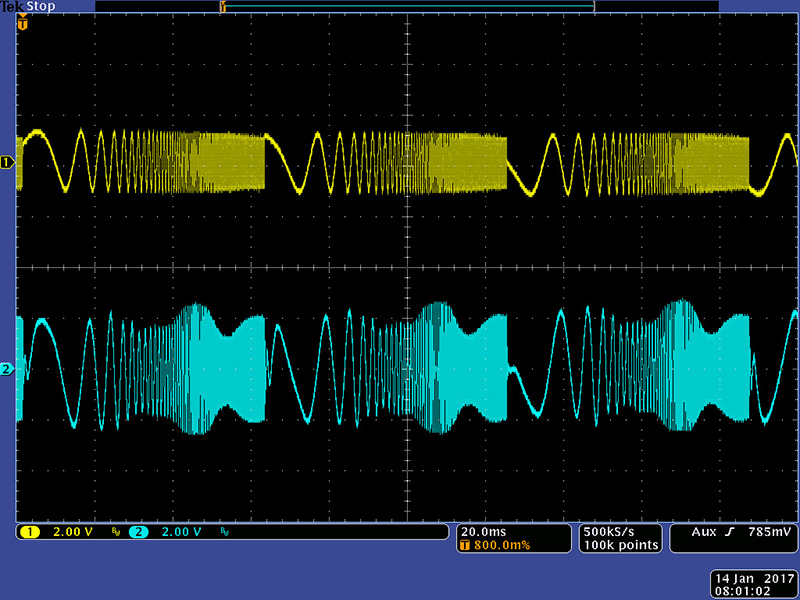
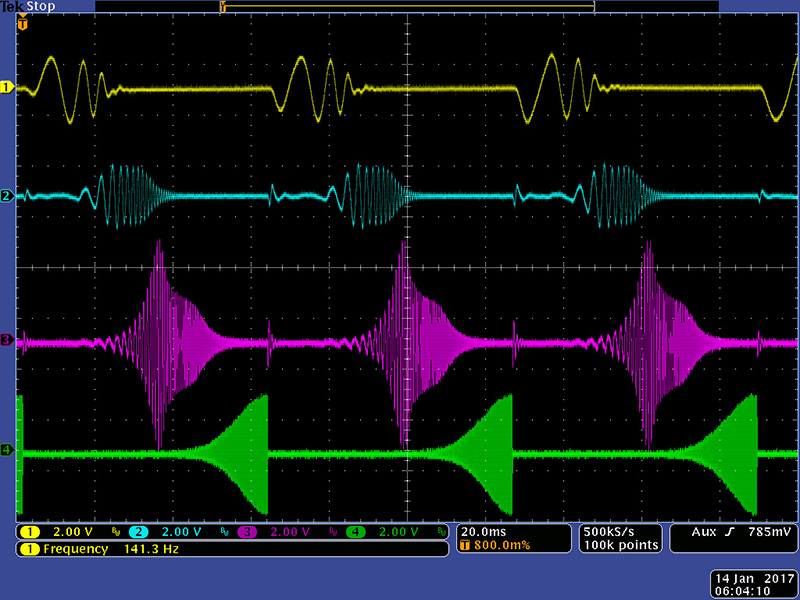
This scope image shows the four channel outputs driven by a swept sine oscillator. The <250 Hz channel and the 250 Hz -1 KHz channels are well behaved. The 1 KHz - 4 KHz channel has a peak and the output amplitude is considerably higher and the >4 KHz channel output is likewise high amplitude.
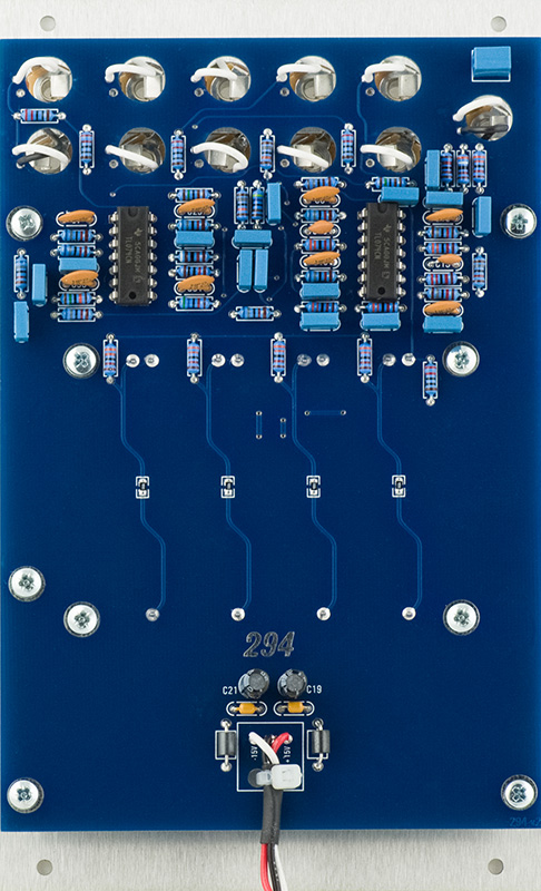
The filter topology consists of 3rd order Sallen-Key low pass and high pass filters utilizing a single op-amp in a voltage follower configuration. Consistent with the design practices of the day, Don included negative feedback resistors bypassed with 100pF capacitors to balance the output offset voltage. However, with JFET input op-amps like the TL074 with low input currents these resistors are unnecessary and make the circuit more prone to cross talk and feedback. Simply removing R7 and C7 and replacing R7 with a link corrects the >4 KHz channel. The other channel feedback resistors and capacitors can be left in circuit or removed and replaced with a link.
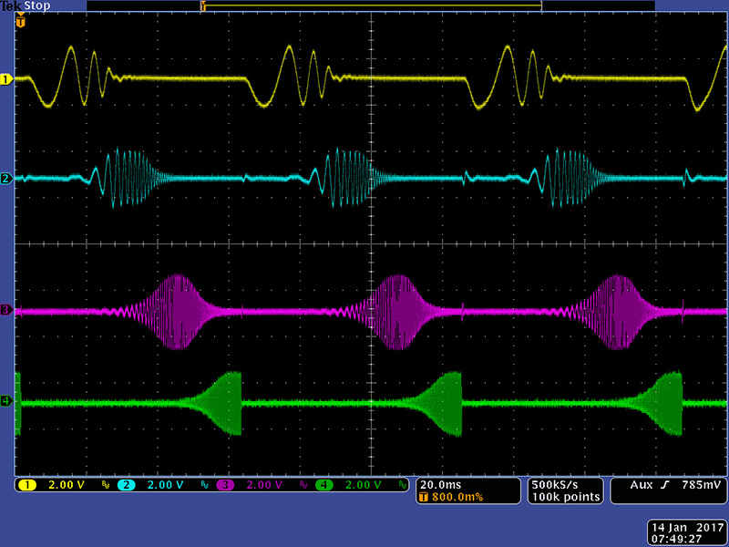
The 1 KHz - 4 KHz channel has a different issue where the damping factor is too low and there is an oscillation resonance at 1.3 KHz. Simulation shows that increasing C4, C5, and C6 from 10 nF to 15 nF increases the damping factor appropriately to about 0.3. However, it is difficult to unsolder these box capacitors once assembled so I chose to change the resistors instead. Changing R4 from 68K to 20K, R5 from 1K8 to 3K9, and R6 from 180K to 39K settles down the oscillation resonance. as shown in this scope image.
This scope image shows the Sum Output of the modified filter. The yellow trace is my swept sine input and the cyan trace is the Sum Out which is reasonably flat.