|
Serge Wilson Analog Delay Module |
|
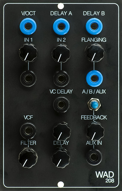
I built a CGS208 Wilson Analog Delay in a Frac format module for a customer. The customer sent me the PCB and a drawing of a concept of the front panel. I did the panel fabrication using a 2mm FrontPanelExpress etched panel.
Construction
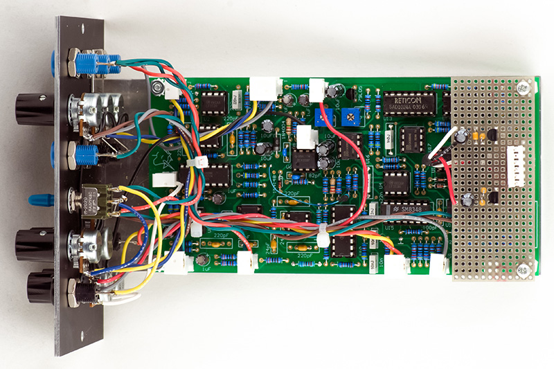
PCB assembly was straightforward. I did cut the run for Trimmer B and replaced it with a 5K trimmer and 4K99 series resistor to eliminate the restriction about turning it CCW more than half. The customer wanted it to operate on +/-15V instead of +/-12V. Because of the rarity of the SAD1024 BBDs I chose to simply add a daughter board with regulators to drop the supply voltage to +/-12V and use a Dotcom connector for power as I didn't want to risk any accidents with these BBDs.
I made a bracket mounted by the banana jacks to mount the panel. I used 0.100" MTA headers to connect all the wiring to the PCB. A few resistors were mounted on the rear to accommodate the MTA headers.
Calibration of the module had issues. There was no S&H pulse on U11 pin 10. The differentiated square wave amplitude was too low to trigger the CMOS gate. I ended up changing C22 to 100 pF and R88 to 22K to generate a sufficient trigger for the pulse.
Trimmers A and B calibrated at the extreme but the A output did not reach unity gain and the B output is lower by design. The A output is from the second BBD section and the B output is from the fourth BBD section so is more distorted. I increased the gain of A out and B out by changing R46 and R47 to 68K.
Trimmer C would not zero both the A and B outputs and the level changes slightly with the delay frequency. I ended up adding a 150K resistor from -12V to IC10 pin 10 to zero B and used trimmer C for A.
Operation
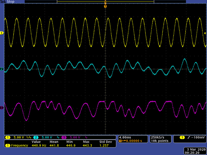
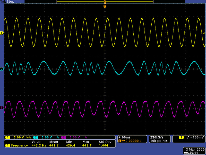
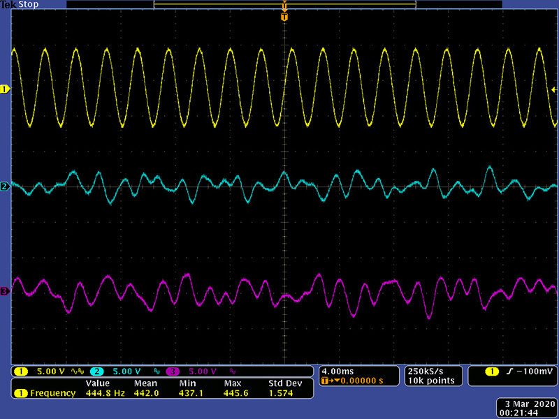
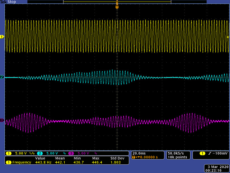
You can get quite a range of sound with the VC Delay, VC VCF and the Feedback controls. Here are various scope images. These next three scope images are the A and B outputs with a single A input, VC delay, and some feedback.
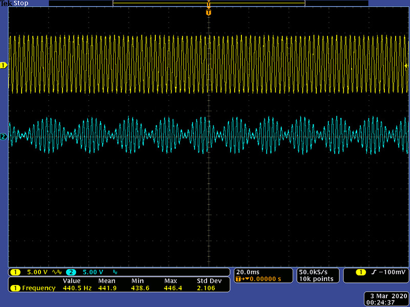
These next two scope images are of the Flange output with a single A input, VC delay, and some feedback.
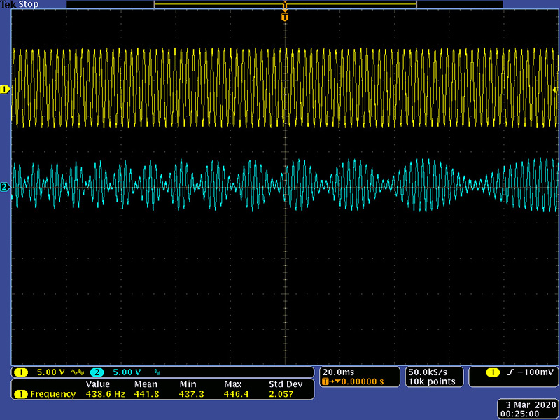
This scope image is the A and B outputs with a single A input and VC VCF.
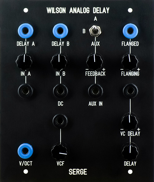
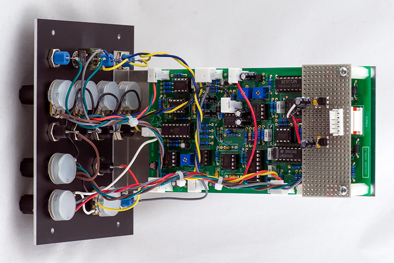
Epilog
I later converted this for the customer to a Synton panel. This is a FrontPanelExpress printed panel.