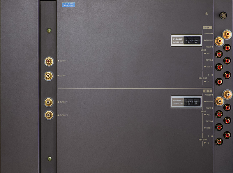
 |
Sony TA-E88 Preamp |
|
This client wanted me to recap, calibrate, clean, and upgrade the connectors on a Sony TA-E88 preamp. This is the Cadillac of turntable preamps. I cleaned PCBs, replaced the capacitors, replaced the connectors, and calibrated the preamp.

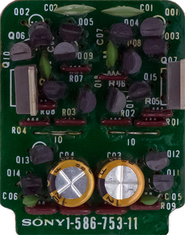
I cleaned the head amp power supply daughter cards and the head load boards which had a lot of flux on them. This image is the head amp power supply daughter card cleaned with the new Nichicon audio grade capacitors.
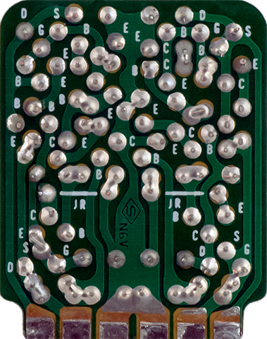
This image is the cleaned head load daughter card.
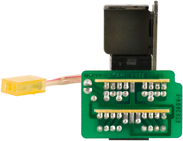
I upgraded the capacitors to Nichicon audio grade gold capacitors and replaced the trimmers with cermet. Calibration was straightforward. This image also shows the replaced gold RCA connectors. The four phono input connectors and the four preamp output connectors will be replaced with chassis mounted connectors on the top cover.
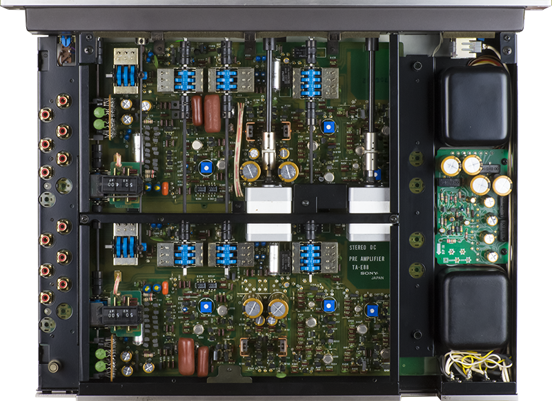
I increased the voltage for the new main filter capacitors to 100V since they were the same physical size and was hopeful that I could run this preamp on 120 VAC. At 100 VAC line voltage the 2SC1061 pass transistor case temperature is 101 °C. The preamp is 22W so there could at most be 5W per main power supply per channel dissipated. The 2SC1061 would be dissipating about 1/3 or 1.67 watts and Tj would be about 110 °C or at 73% of the absolute maximum rating. Increasing the line voltage to 120 VAC would increase Tj beyond the safe operating area with the existing heat sinks. There is limited room and no ventilation for the chassis so a 1.2:1 line transformer is required to use this preamp on 120 VAC.
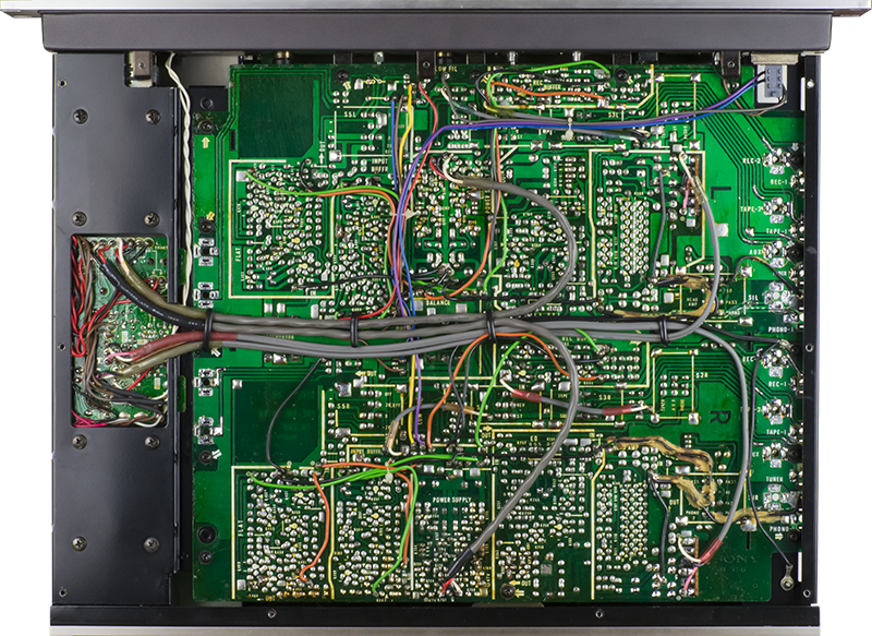
The RCA connectors had previously been replaced and traces cut to accommodate the footprint. This image shows the repairs to the PCB to restore all cut traces.
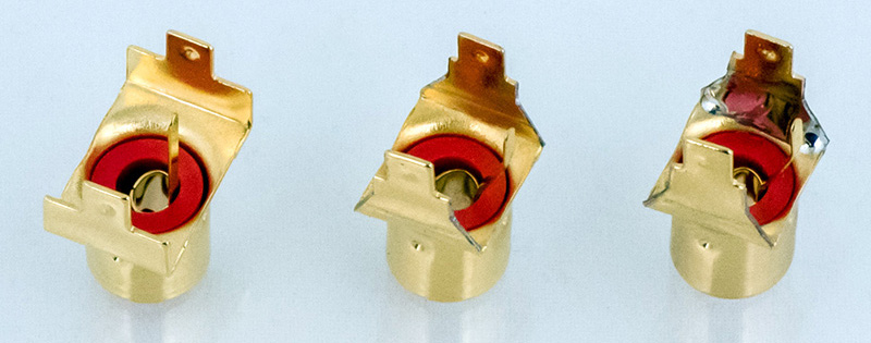
The stock gold PCB mounted phono jacks fracture with repeated insertions so they had been replaced with a Cu-Ni jack similar to a Pro Signal PSG08307. The PCB mounts flush to the chassis so there is no room for any type of thru-chassis jack. A Mouser 161-R239A2-E PCB-mount gold plated jack can be reformed to fit. The stock PCB tabs are spaced too wide at 13 mm and the width of the tab is too wide to clear the chassis hole (left jack). You can bend the tabs flat and rebend them at the jack to narrow the tab spacing to 10mm (center jack). Bending the tab flat weakens the metal along the fold line and can be reinforced with solder on the inside (right jack). Reformed this way the three tabs fit the PCB slots perfectly (the stock jacks had four tabs).
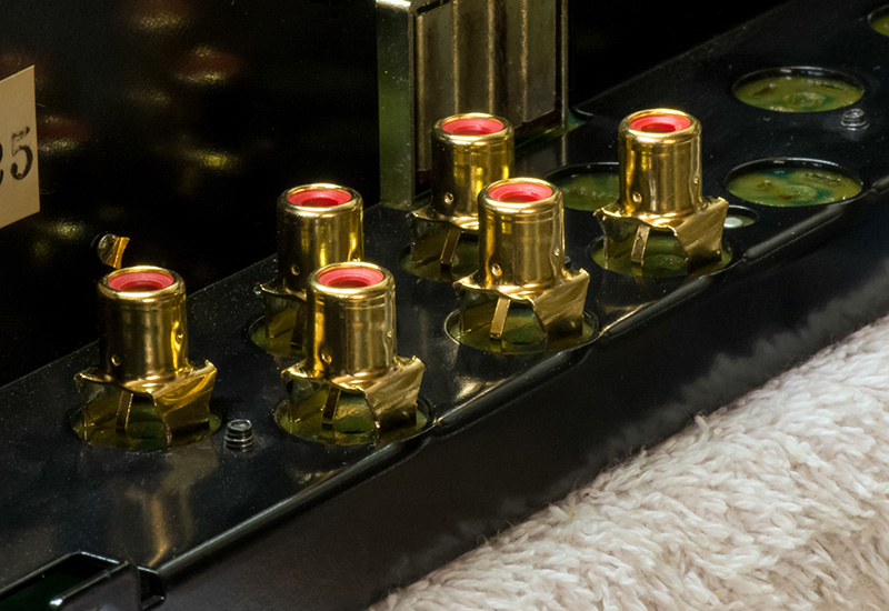
The jacks fit quite well but sit higher than the stock jacks. The PCB is secured to the chassis with several screws along the connector but force applied to the jacks does flex the PCB so care needs to be taken when cabling to the preamp.
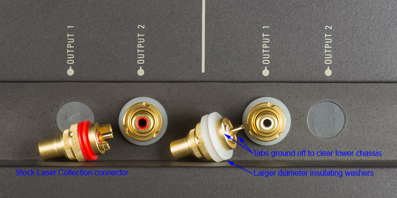
I used Laser Collection gold plated chassis mount jacks for the phono inputs and the preamp output jacks. I mounted the jacks to the top cover and had to wire them to the PCB with the cover installed. This makes removal of the top cover more difficult but provides a more robust connector.The top cover holes are too large for the stock insulators so I used two larger nylon washers with a smaller sandwiched washer to mount them. The lower tabs were close to the bottom chassis so I removed them.
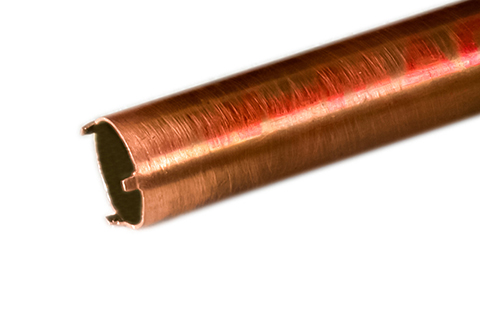
I made a 3 pronged wrench from 1/2" copper pipe to tighten the RCA jacks securely.
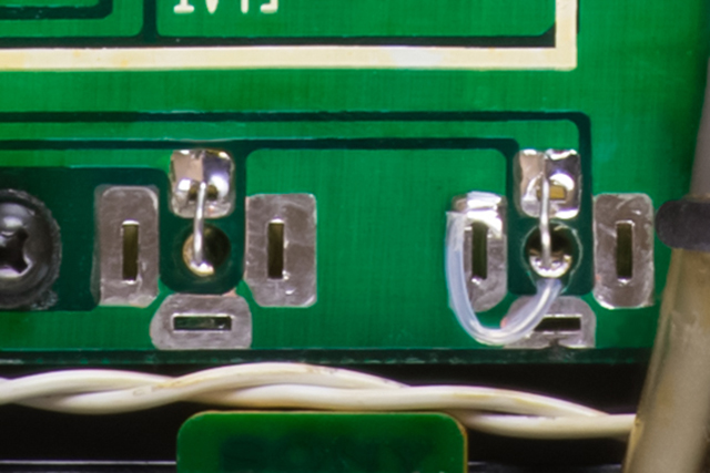
I connected the grounds of pairs of jacks (e.g. left channel phono1 and phono2) and used bus wire with insulation to connect through the PCB. I looped the wired and soldered it to the pads I elongated the center hole just enough to allow clearance for the ground wire..
All of the jacks fit nicely on this preamp. The red and white plastic inserts around the PCB mounted RCA jacks need to be shortened since these jacks sit higher. I removed them and will let the owner decide if he wants to cut and install them.
