|
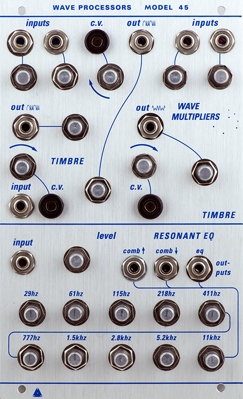
Vedic Scapes Wave Processor 45 |
|
This module is basically a combination of a Serge Wave Folder and Resonant EQ module in a Buchla-format 4U panel.
Operation
The Serge Wave Folder consists of three separate sections. This module incorporates two of the Serge middle section and the bottom section. The left and center sections are based on the Serge middle section circuits. The wavefolding is dependent upon the signal level, so the left section attenuators allow precise setting of the timbre control.
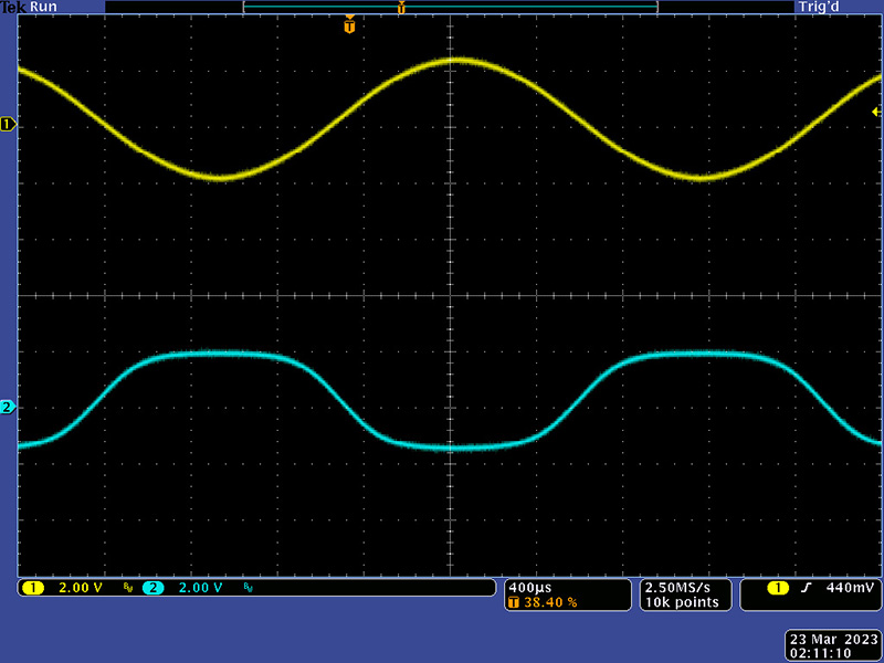
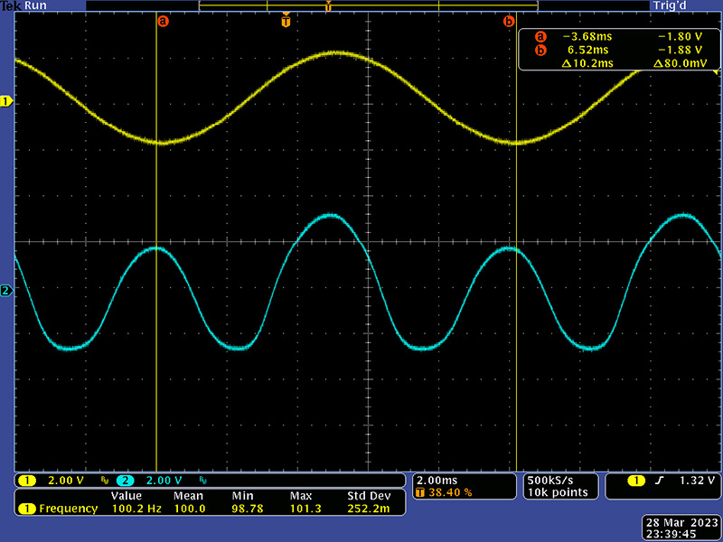
This scope image shows the input level of the left timbre section adjusted so there are no folds.
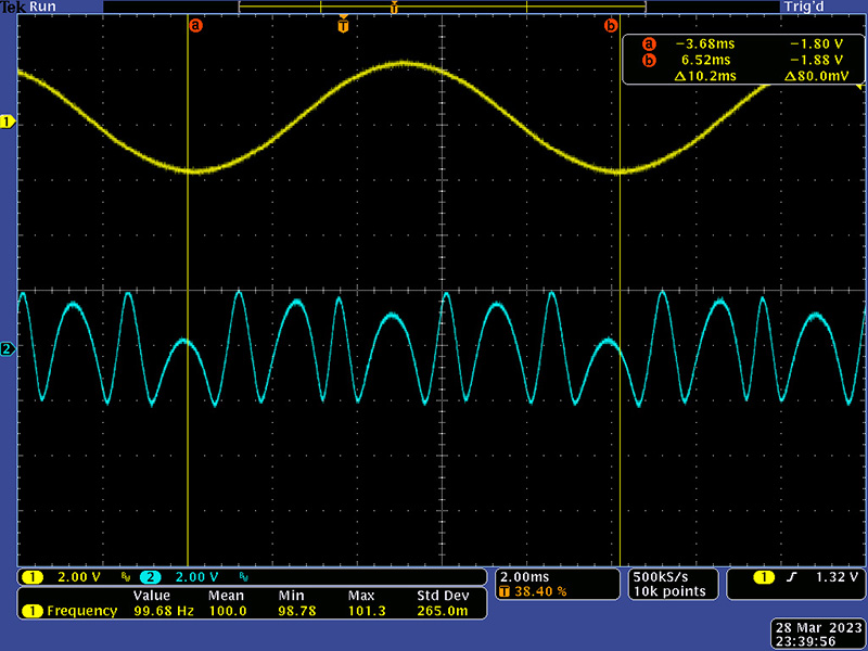
This scope image shows the input level of the left timbre section adjusted with maximum timbre. I adjusted the CV input so a 10V CV produced the same range as the timbre control.
The middle section has no attenuator so a 4V pk-pk signal begins to fold slightly. This is the same as the left section with the attenuator on full CW.
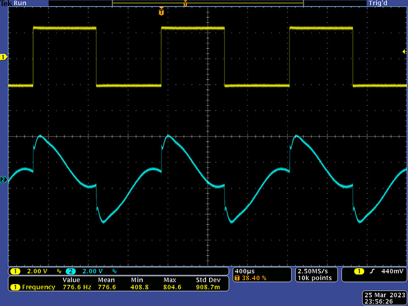
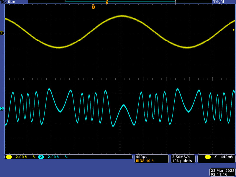
This scope image shows a 4V pk-pk signal has more severe folding with timbre on maximum.
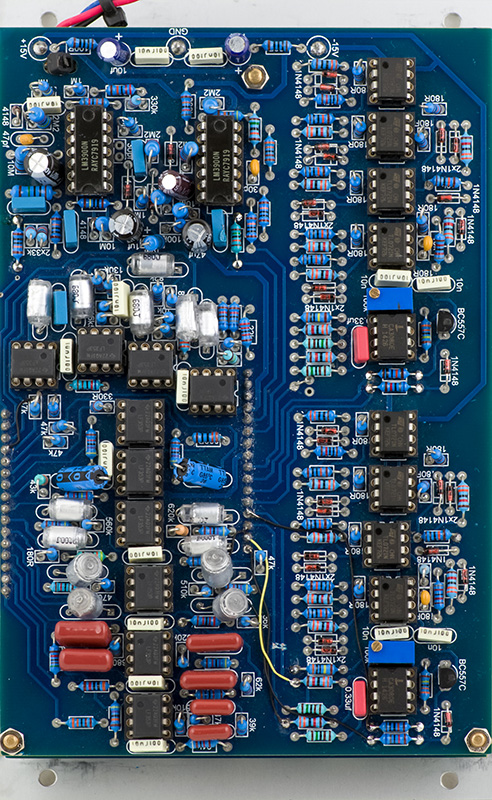
The right section is based on the Serge bottom section circuits which creates even folds. I was lucky to have a Serge Wave Multiplier in the shop to compare against.. The wave folding is dependent upon a correct signal level, so the input attenuators allow precise adjustments for correct timbre control. This portion of the PCB had several layout errors that were not documented in the build instructions.
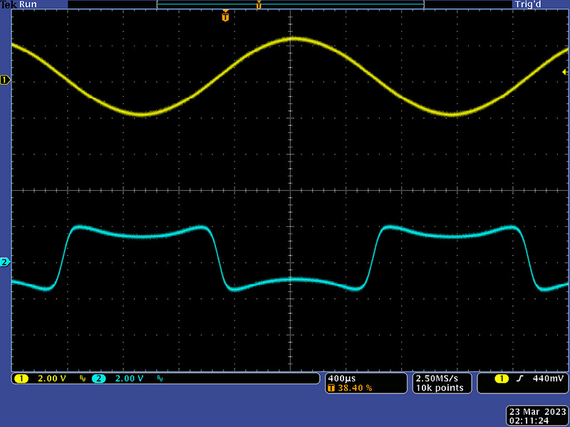
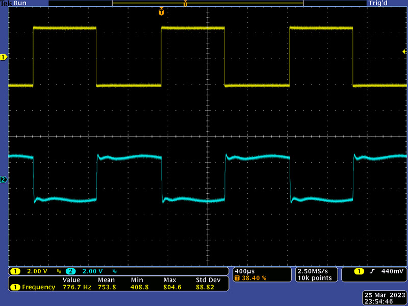
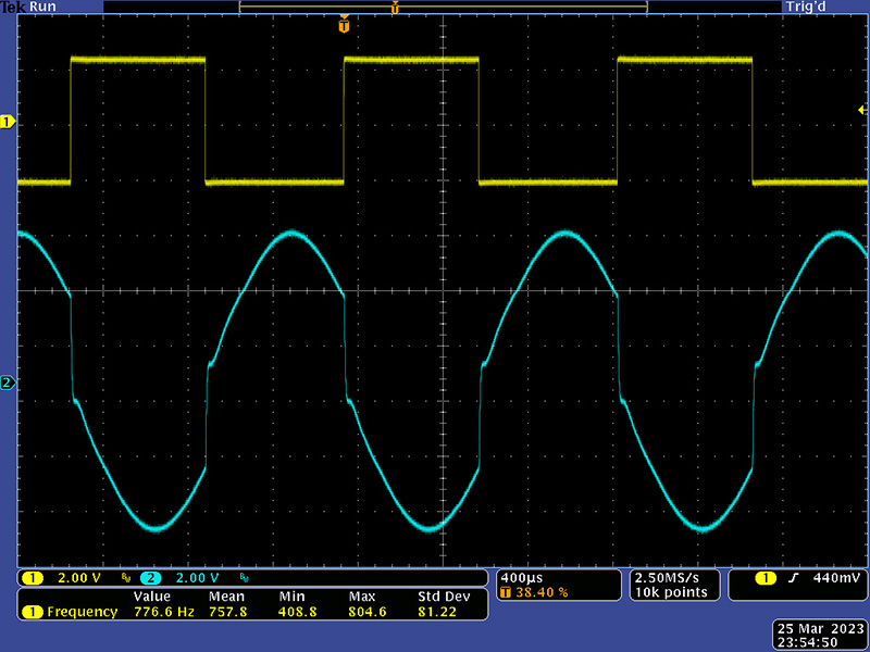
This scope image shows the input level of the right timbre section adjusted so at minimum timbre there are no folds.
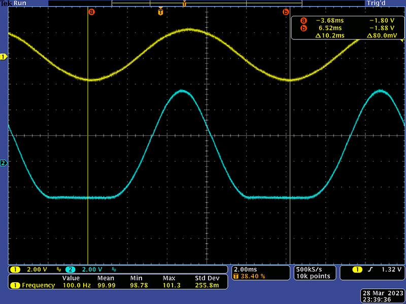
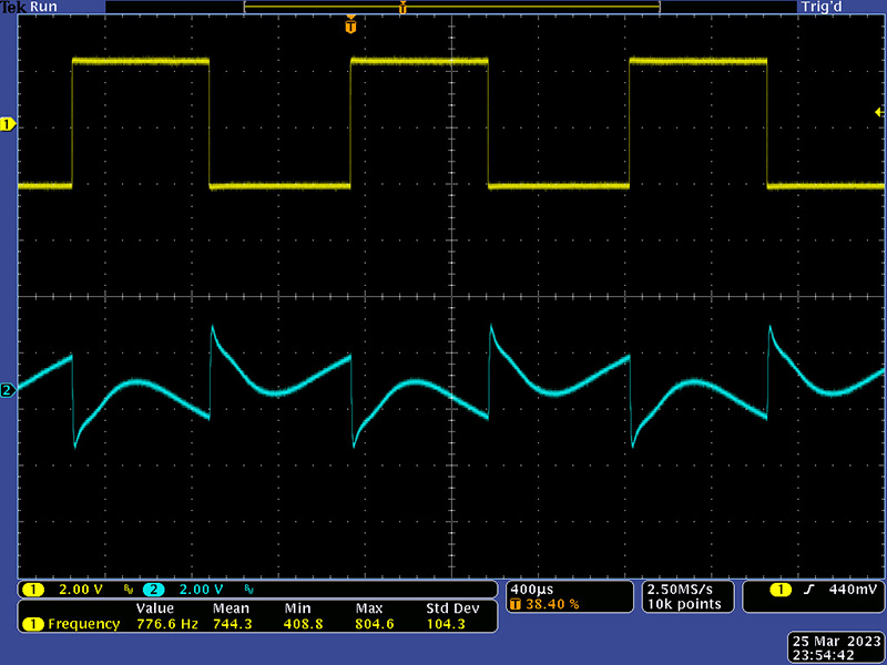
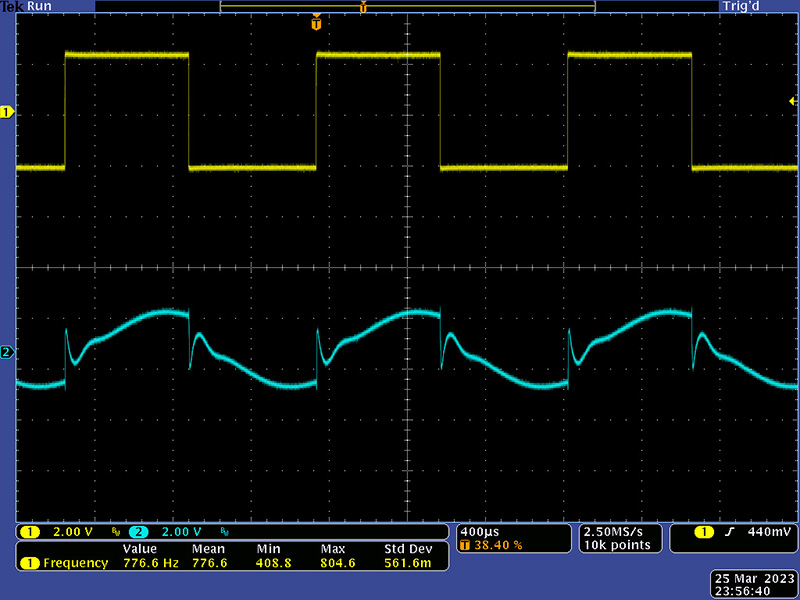
This scope image shows the right timbre section adjusted so there are two folds.
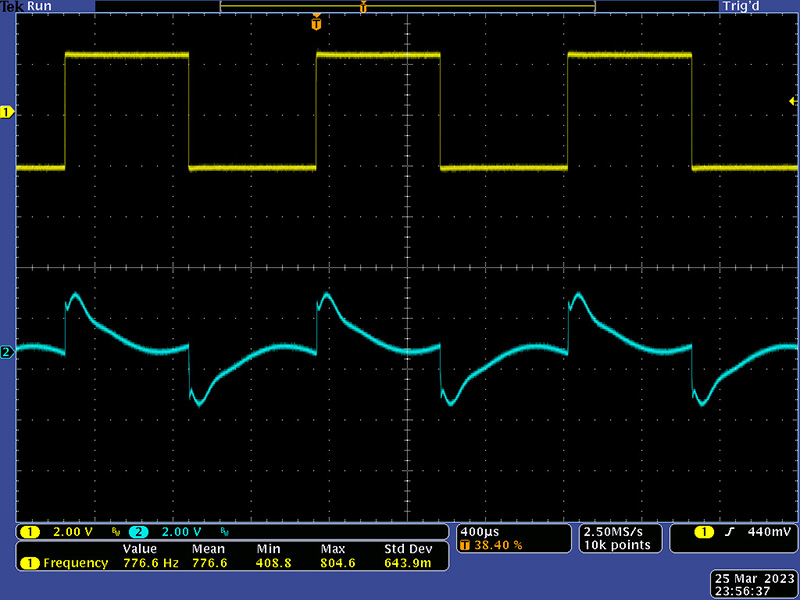
This scope image shows the right timbre section adjusted so there are four folds.

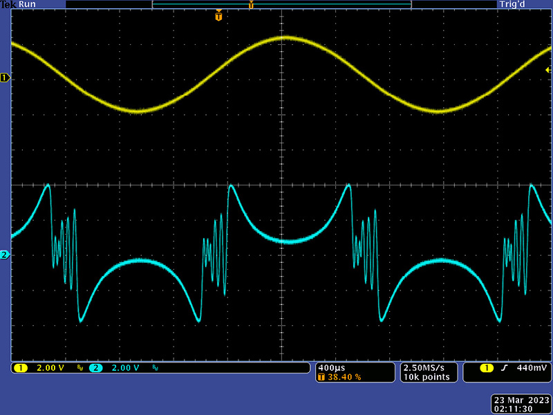
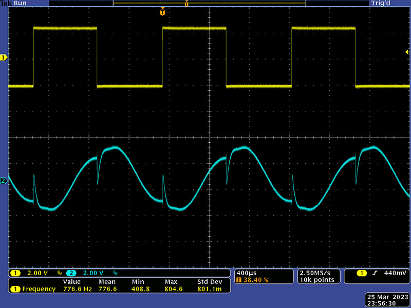
This scope image shows the right timbre section adjusted at maximum for eight folds. I also adjusted the CV input so a 10V CV produced the same range as the timbre control.
The resonant EQ is a ten-band filter. The middle frequency bands are spaced at an interval of a major seventh. There are three outputs, two of which consist of alternating bands. The Comb ↑consists of the 61 Hz, 218 Hz, 777 Hz, 2.8 kHz, and 11 kHz bands. The Comb ↓consists of the 29 Hz, 115 Hz, 411 Hz, 1.5 kHz, 5.2 kHz bands.
The controls are a bit unique. When set to mid position, the output of the equalizer is flat. When set to the left, the output is cut. When set to the right, the output is boosted and becomes a bit resonant. This scope image shows all of the frequency controls set to mid position.
This scope image shows just the 777 Hz control set to minimum.
This scope image shows just the 777 Hz control set to maximum which produces a lot of gain.
The module doesn't provide a hard split between the comb filter outputs. This scope image shows the Comb ↓output with the 777 Hz control set to minimum.
This scope image shows the Comb ↑output with the same settings.
This scope image shows the Comb ↓output with the 777 Hz control set to maximum.
This scope image shows the Comb ↑output with the same settings.