|
Blacet Research |
|
5U Large Format Module
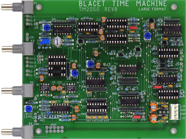
I built a second Time Machine with a Blacet large format Rev-B PCB as discussed on the Electro-Music forum and also on the Muffwiggler forum. I bought the PCB, 5U panel, bracket and a MN3005 BBD that I bought from a fellow Synth-DIY'er. The Rev-B PCB incorporates all three of the modifications that I added to my Rev-A PCB.
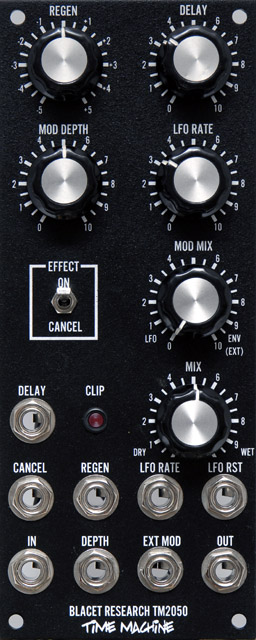
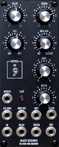
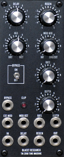
The control locations and nomenclature on the Blacet panel (left) are different than the Stooge panel (right). Many of the jacks locations are different but the nomenclature is more similar.

I bought my parts from Mouser. Some of the parts are difficult to find so I had to find substitutes.
Mouser Rev-B Time Machine parts list
|
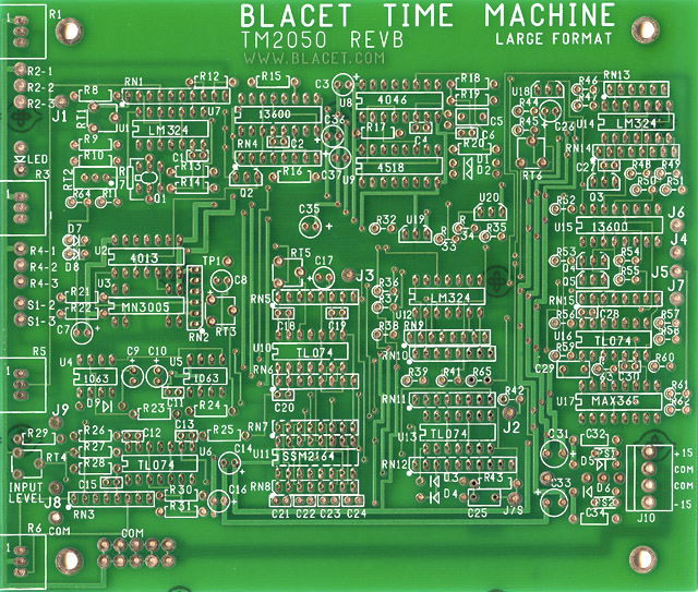
Time Machine Rev-B PCB Note: The three CMOS logic parts (4013, 4046 and 4518) must be 15 volt parts. Do not use HC or HCT parts which operate on 5 volts. See my Modular Synth Tips page for more information on the various CMOS families.
Substitutions:
SSM2164 protection modifications: Note: The SSM2164 quad VCA exhibits a catastrophic failure mode when the V+ pin is powered and the V- pin is disconnected (e.g. disconnected means open, not at ground potential). There is documentation on this failure mode on Neil's Webbly World page. The modification to prevent this failure is to add a schottky diode with the anode connected to pin 9 (e.g. -15 volts) and the cathode connected to ground to provide a path for current to flow the negative supply is disconnected. The Time Machine already has diode D6 wired this way for reverse voltage protection. All you need to do is change D5 (and D6) from a 1N4002 to a schottky 1N5817. This is not included in the parts list.
Potentiometer modifications: I substituted 100K potentiometers instead of the 50K since I have a large inventory of BI Technology potentiometers. These modifications are only for 100K potentiometers and are not included in the parts list.
|
With a more semi-log Delay control contour (because of the 100K input impedance across the wiper) the delays were just a bit shorter than on my original TimeMachine. The delay was ~30 mS (vs. 50 mS) with the Delay control set at 3.5 and ~ 195 mS (vs. 250 mS) with the Delay control set at 6.5. The maximum delay remains unchanged.
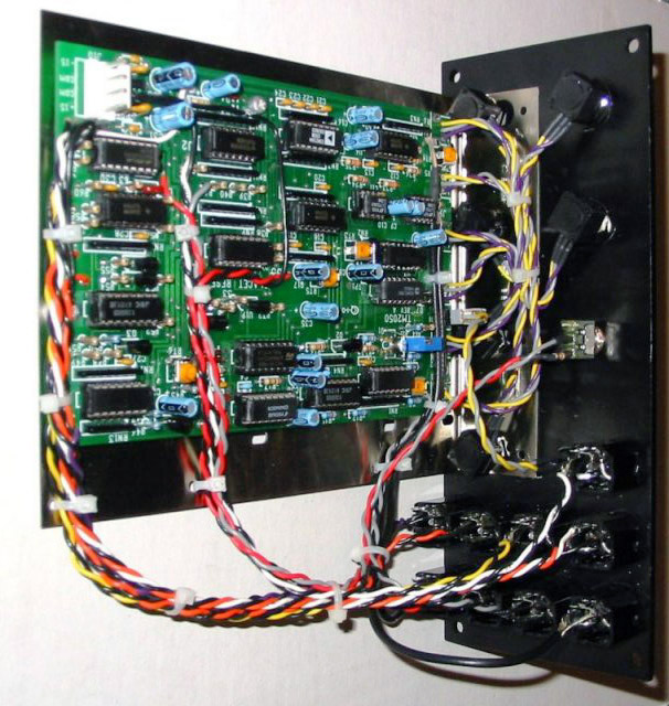
I only used sockets for the MM3005, MAX365, SSM2164, LM13600's, and the CMOS logic parts. This large format PCB really reduces the panel wiring. The tempco resistor just fits over the larger MAT03 expo converter.
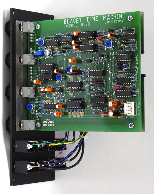
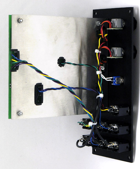
The bracket faces the center of the module and the wires come through cutouts in the bracket. This makes it more difficult to wire and repair the PCB although the finished module does have a cleaner appearance. I used serrated edging around the bracket cutouts to protect the wires from the metal edges.
5U Module Conversion
I built my first Blacet TimeMachine using the Rev-A PCB kit from Blacet and a 5U panel and bracket from Stooge.
I installed the Blacet modification for protection from overload of the input levels. I also installed the Stooge modifications for a bypass switch and the Delay CV protection. Both modifications work fine.
There are a number of documents and photos on the Stooge Time Machine page for assembly and calibration.
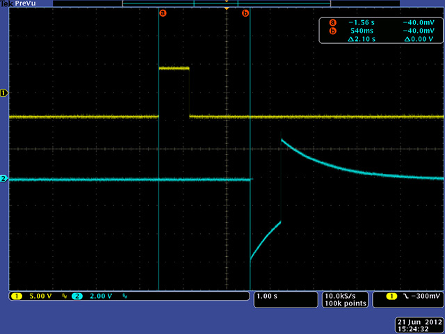
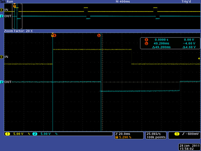
I measured the delay at two different settings. The delay was ~50 mS with the Delay control set at 3.5, corresponding to 10:30. Note the delayed output pulse is inverted and reduced in amplitude. The reduced amplitude is helpful when using regeneration or mixing with dry to keep close to a 10 volt pk-pk output.
The delay was ~250 mS with the Delay control set at 6.5, corresponding to 1:30. The maximum delay setting was just over 600 mS.
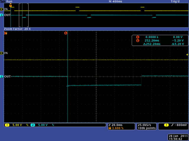
The maximum delay is just over 2 seconds. I used a LFO with a long time period and narrow pulse so I could correlate the input and output signals.