|
Modular Synth Tips |
|
Module Power Consumption
Here is my spreadsheet with the power consumption of many purchased modules. This information is from either the module specifications or was measured.
Module power consumption spreadsheet Updated
How To Get Started In Synth DIY
People will look at my pages and then send me an email asking how to get started in Synth DIY. I finally decided to document my typical response here.
The first decision is whether to go modular or all-in-one. The difference is whether you want the ability to expand your system or create custom patches. For an all-in-one beginning system you might want to check out the Music From Outer Space Sound Lab Mini-Synth Mark II, or the Oakley Sound TM3030 bass line synth or the Elby Designs ASM. I would also be remiss if I didn't mention the PAiA Fatman although it operates on V/Hz but with MIDI input it is not really an issue.
If you decide to go modular, you need to decide what format. There are many different formats but the main ones are 5U (e.g. MOTM), 5MU (e.g. Moog and now synthesizer.com), Euro, and Frac. Matson Mini Modular also makes a very small sized format.
The main difference between 5U/5MU and the other formats is the size of the jacks. Most 5U/5MU use 1/4" jacks while the other formats use 3.5mm jacks (some 5U modules will use banana jacks similar to the original Buchla) . I chose 5U because I wanted the reliability of 1/4" jacks and I believe it is the easiest DIY format with flat 3mm faceplates. As mentioned on my home page, I grew up with ARP who used 3.5 mm jacks and I just prefer the 1/4" format. Note that each format may have a different power connector or even power supply voltages which adds another complication to the mix.
Next you need to decide what DIY really means. There are assembled modules, kit modules, and sources for PCBs. Kits may or may not include detailed instructions. Usually PCBs just provide a parts list and schematic. Sometimes there are errors in both. I've never understood why someone would go to the trouble to design and sell a PCB and not bother to correct the documentation. Oftentimes there are forums on Muffwiggler or Electro-Music where you can find the errata - if you want to peruse 32 pages of the forum!
Synthtech designed and sold great 5U modules in assembled and kit form. They have since moved on to Euro format although he usually will sell an assembled PCB for a DIY module (which is what I buy for my 5U modules). Some of his 5U format is now sold by synthCube. Synthtech is noted for quality of design and completeness of assembly instructions. Although some modules are complex, the instructions are suitable for beginners.
Wise Guy Synths was one of the first 5U DIY websites created by Larry Hendry. Larry has died but his site is still up for reference. He was a great resource and did custom silk screened panels at one time.
Blacet sells kits in Frac format. Their instructions are less complete. You need to be able to recognize all components and install build the board. His instructions cover any calibration and check out necessary. John died and Synthcube is working continue to offer his designs.
Oakley Sound sells PCB with fairly good instructions although they do not include step-by-step. Since they are PCB only, you can choose the format. Another advantage is they have a relationship with Krisp1 which sells assembled modules.
Synthesizer.com sells complete 5MU modules at a reasonable cost.
Modcan also sells 5U modules but typically at a higher prices.
Cat Girl Synth used to sell PCBs but they are now handled by Elby Designs. They are typically single sided which beginners may have trouble with as too much heat will lift pads, especially for any repairs. The documentation is what is on the web site, typically a parts list and schematic. There is also a Ken Stone forum on Electro-Music.
synthCube sells modules, some parts, PCBs, and front panels. It is for the real DIY. They provide excellent customer support.
Elby Designs is another great DIY resource and has kits for many different vendors as well as DIY items.
Cyndustries was a multi-format vendor but now seems to be just a web portal on modular synthesizers.
Music From Outer Space has quite a large website. Ray died but synthCube sells some of his products. His site has a good Analog Synth 101 tutorial. There is also a Ray Wilson forum on Electro-Music.
Thomas Henry has designed many different modules. Magic Smoke Electronics has published some of his papers which provide a good introduction and theory for his designs. Thomas Henry does not sell PCBs but some are sold by Magic Smoke Electronics and others are sold by synthCube. There is also a Thomas Henry forum on Electro-Music.
Matson Mini Modular is a vendor who has a very small module size and has a reasonable number of modules.
Front Panel Express is a machine service where you can get really nice front panels made for a costly sum but they do look nice. You can use their software to design your front panel. I have made some panels where I simply printed the image and glued it to 3mm aluminum. My TH-301 uses such a panel which can be seen here.
I personally buy my parts from Mouser and many of my module pages have BOMs with Mouser part numbers. Note that since RoHS many of the part numbers change slightly so you might have to do a bit of research to find the current part number.
This is the summary I usual give when asked. Time for you to do some reading. I would suggest you start with on Muffwiggler or Electro-Music forums. Find some posts that cover your interests and then read them for a while. Good luck.
VCO Calibration Method
I have always disliked VCO tuning. I've used oscilloscopes, frequency counters, and beat frequencies to try and make it easier. The issue is changing the scale adjusts the base frequency requiring constant retuning.
I picked this method up in some forum on the web and it works great. It's the divide by 2 method. You use a summation circuit to add 1.000 volts to the CV. When tuned correctly, this will increase the VCO frequency by one octave, or double the frequency. At the same time you add a divide by two circuit to half the frequency. You simply adjust the tuning until there is no perceptible change in frequency when you step up and down an octave.
I have all the modules in my system for this setup. I used a Larry Hendry JLH-822 VC Shift which will add or subtract an octave or semitone from a control voltage, a MOTM-120 Sub-Octave Multiplexer with the Tellun sub-octave outputs, and the MOTM-700 VC Router. Patch the setup according to the diagram. Set the Mix Out for Mix A Square. Adjust the MOTM-700 Switch control so the router selects IO B when you switch up an octave. Switch the octave up and down and tune until there is no change in frequency. Simple! Of course you could use this same method for two to four octaves. Just select the appropriate output from the MOTM-120.
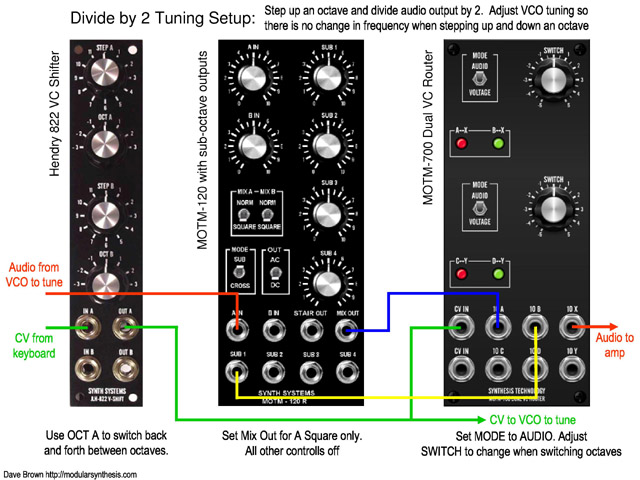
Divide by 2 tuning setup document
XY Frequency Plots
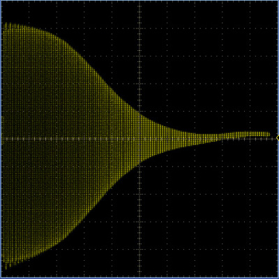
I was working on a René Schmitz Korg MS20 VCF clone and wanted to verify the LP and HP functions. One easy way to do this is to use your oscilloscope in XY mode. Connect an LFO ramp to sweep a VCO which drives the filter. Connect the LFO ramp also to the X axis and connect the output of the filter to the Y axis. You get these nice looking plots showing the frequency response. The horizontal axis represents frequency since increasing voltage increases frequency. The vertical axis represents amplitude.
 |
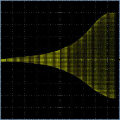 |
| Low Pass Filter Response | High Pass Filter Response |
uA726 Replacement
Many of the Buchla, and other designs, use a uA726 which are hard to find and expensive parts. Most designs use a typical configuration with a voltage divider driving the base of the expo-pair. I have been using discrete transistors and a tempco in several of these modules. I simply use tape-and-reel 2N3904 transistors which will be fairly matched. They will fit the base profile of the uA726 with two bent pins and two flying wires. The transistors can be epoxied together. The lower resistor in the divider can be changed to a tempco which can be epoxied to the top. If the lower resistor is not of a convenient value for a tempco, usually the resistors in the CV circuitry can be scaled to adjust. This is my wiring diagram for such a replacement.
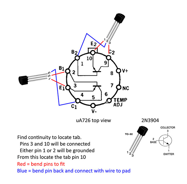
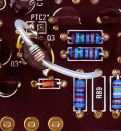
Here is a photo of such a replacement on a Buchla 258 Dual Oscillator.
SSM2164 Failure Mode
The SSM2164 quad VCA exhibits a catastrophic failure mode when the V+ pin is powered and the V- pin is disconnected (e.g. disconnected means open, not at ground potential). The SSM2164 is used in many designs including the Blacet Research Time Machine and Magic Smoke Electronics TH-201 Mankato Filter, as well as in my DJB-014 Output Interface which uses the Charlie Lamm 'Mike Irwin" VCA design.
The modification to prevent this failure is to add a schottky diode with the anode connected to pin 9 (e.g. -15 volts) and the cathode connected to ground to provide a path for current to flow the negative supply is disconnected. Both the Blacet Research Time Machine and the Magic Smoke Electronics Mankato Filter have diodes connected this way for reverse voltage protection. Simply changing these diodes to schottky 1N5817 diodes will also protect the SSM2164.
There is documentation of this failure mode on Neil's Webbly World page. My thanks to Neil Johnson and Oscar Salas for doing the research.
Some synthesizer modules use CMOS logic parts. There are multiple families of CMOS logic parts but they fall into two main groups: 15 volt compatible and 5 volt compatible. The original 4000 series CMOS parts worked over a wide range of supply voltage up to and including 15 volts. Later a new family of CMOS designated 74HC and 74HCT was introduced to be compatible with TTL circuits and will only operate on 5 volts. Many synthesizer designs use the 4000 series-compatible parts and operate on 15 volts. You can only interchange 4XXX and 74HC/HCT parts IF the operating voltage is 5 volts. Vendors sometimes use unique nomenclature for their CMOS families. You need to check the data sheet to verify the operating voltage range.
One example of this is the three CMOS logic parts used on the Blacet Research Time Machine. The parts list calls out a 4518 BCD counter, a 4013 dual flip flop, and a 4046 phase locked loop. These parts operate on +/-7.5 volts (e.g. 15 volts) and must be 15 volt CMOS compatible.
As an example, a quick check of Mouser shows at least four different parts for a DIP 4013 counter and all are 15 volt compatible.
| Mouser P/N | Vendor P/N | Vendor | Voltage |
| 771-HEF4013BPN | HEF4013BP,652 | NXP Semiconductor | 15 volt |
| 771-HEC4013BT118 | HEC4013BT,118 | NXP Semiconductor | 15 volt |
| 595-CD4013BNSR | CD4013BNSR | Texas Instruments | 15 volt |
| 511-4013 | HCF4013BEY | STMicroelectronics | 15 volt |
A quick check of Mouser shows at least eight different parts for a DIP 4046 phase lock loop but only three are 15 volt compatible.
| Mouser P/N | Vendor P/N | Vendor | Voltage |
| 771-HC4046AN652 | 74HC4046AN,652 | NXP Semiconductor | 5 volt |
| 771-HEF4046BPN | HEF4046BP,652 | NXP Semiconductor | 15 volt |
| 771-74HCT4046AN | 74HCT4046AN,112 | NXP Semiconductor | 5 volt |
| 595-CD74HC4046AE | CD74HC4046AE | Texas Instruments | 5 volt |
| 595-CD4046BEE4 | CD4046BEE4 | Texas Instruments | 15 volt |
| 863-MC74HC4046ANG | MC74HC4046ANG | ON Semiconductor | 5 volt |
| 595-SN74LV4046AN | SN74LV4046AN | Texas Instruments | 5 volt |
| 595-CD4046BE | CD4046BE | Texas Instruments | 15 volt |
You need to know your CMOS parts before using them in a DIY project!
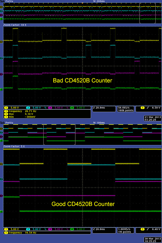
Any time I do a vintage repair that includes 4000 series logic I immediately start by checking those parts. Early 4000 series parts seem to go semi-bad. They don't stop working, they just stop working correctly. Here is a CD4011 in a clock circuit that still oscillates but just not at the right logic levels. The output logic low level is up at 3.72 volts.

Here is a CD4520B used as an address counter for a memory clocked by the above oscillator. You can see the bad one counting correctly but the outputs are only valid while the clock is high - bizarre. I tried a NTE4520B replacement which exhibited similar issues intermittently - that's strange. I found that a vintage 1985 part worked correctly. The clock input is grounded and the enable pin is clocked but both go to an internal nand gate so it shouldn't matter which is used. Weird - welcome to the world of 4000 series CMOS.
MOTM Power Cables
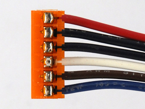
I make my own MOTM power cables. I strip the ends of the wire, tin them, and then press them into the housing. I then solder the wires rather than rely upon the press fit. It's easier to solder rotated 90 degrees so the wires are horizontal. This helps keep the solder from wicking down the connector. Here is a 6 conductor MOTM power cable.
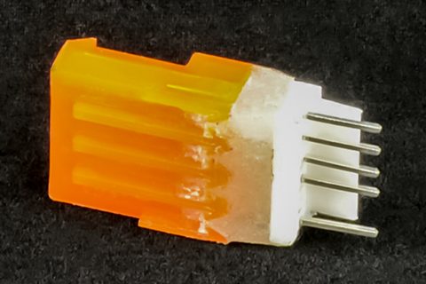
Here is a photo of the soldered MTA connector. This works very well.
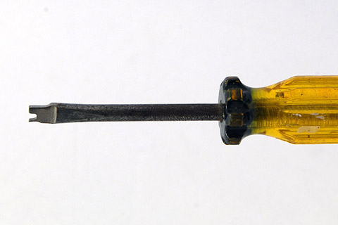
I made this simple punch-down tool from a screwdriver. It helps press the wire through the strain relief and into the connector. It does not make a good electrical connection. The wires must be soldered.
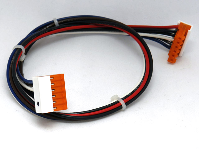
Dotcom Power Cables
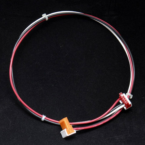
I make Dotcom power cables by using a MOTM 0.156" MTA connector on one end and the Dotcom 0.100" MTA connector on the other end. This photo shows a +/- 15 volt cable. I solder the 0.100" MTA connectors the same way but simply use a small screwdriver to press the wire in. I flatten the insulation at the 0.100" MTA end with pliers so it will fit through the smaller wire openings. I have to use magnifying glasses so I don't damage the housing when soldering.
MOTM-to-Dotcom power cable diagram
I also make Dotcom-to-MOTM adapters by soldering together the appropriate connectors. Then I make a form and fill the space between them with epoxy.
MTA Interconnect Cables
I make 0.100" MTA interconnect cables the same way using a screwdriver to press the wire into the housing and using magnifying glasses to not damage the housing when soldering. I use them on modules that have a lot of panel wiring.

The MTA connectors have a wider top than base so there must be adequate clearance around the PCB header. If there is limited space I have to use the FCI mini-latch connectors which require crimping the individual wires and inserting them into the header.
![]()
Soldering, Cleaning, and Inspecting PCBs
The number one problem I find in doing DIY module repairs is soldering issues: unsoldered pins, incomplete soldering, or solder bridges. It is absolutely essential to inspect each pad using magnifying visors to verify a smooth, shiny, and complete solder joint. It is difficult to inspect pads with flux so I always clean the PCB prior to inspection.
I always follow a pattern when soldering. I start with the lowest height parts (e.g. axial resistors and diodes), then move to each successively taller part in order. Usually sockets and ICs are next, followed by capacitors, then transistors, and finally connectors. I leave off trimmer resistors, switches, polystyrene capacitors, and any other non-washable parts for after I clean the PCB.
For resistors, capacitors, and diodes I put each part on and bend the leads slightly away from each other to hold the part on the PCB. I only do about 5~6 parts and then solder only one leg of each part. That will hold the part on the PCB and I bend the other lead back straight and solder it. I don't like bent leads as sometimes there isn't a lot of clearance to the next run. Then I cut all the leads off and reflow each pad again so the solder flows over the end of the lead.
For sockets I solder the opposite corners and then turn the PCB over and inspect to see if they are all laying flush. Sometimes they a bit high and it is easy to reflow the pin and push the socket flush. Often IC holes are large and it takes a lot of solder. I use a reasonable amount of solder but generally don't fully fill up the hole. When all the pins are soldered, I go back and add just a bit more solder to each pin to fill them up.
For ICs the leads are typically bent. I use IC pliers to push the pins straight and insert them into the PCB. The leads spring back and hold the IC tight. I use the same technique as for sockets, except I only solder every other pin. That way I give the pin time to cool prior to soldering the adjacent pin.
For transistors I press them into the PCB and solder the middle lead. Then I turn the board over and make sure each transistor is straight, then I solder the other two leads, clip them, and reflow the solder.
For connectors I treat them like sockets. Usually the holes are large so I use a reasonable amount of solder on the first pass and add more on a second pass.
I use Kester 331 water soluble core .020" (0.5mm) diameter #24-6337-6401 that can be bought at Mouser. The smaller core is a tradeoff to work with both thru-hole and SMT parts. I generally wash the board at periodic intervals. I wash the PCB, both top and bottom, with a toothbrush under warm water.
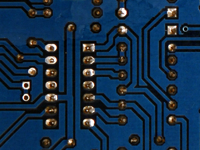
After washing the pads are easier to inspect. First I hold the finished PCB up to a bright light and see if there is any visible light shining through (I would normally add solder to each of the vias but this PCB has solder mask over them). Then I use magnifying visors and inspect each pad. I've soldered every pad twice and since I've reflowed over the cut leads there are no shadows. The pads in this photo are easy to verify a smooth, shiny, and complete solder joint.
After washing, I add trimmer resistors, switches, polystyrene capacitors, wiring, and other non-washable components. I use left over MOTM Kester 245 no-clean .031" (0.8mm) diameter solder #24-6337-8802 which can also be bought at Mouser. I use the larger core since this solder is typically used for switches, potentiometers, and wires..
Most Common Repair Issues
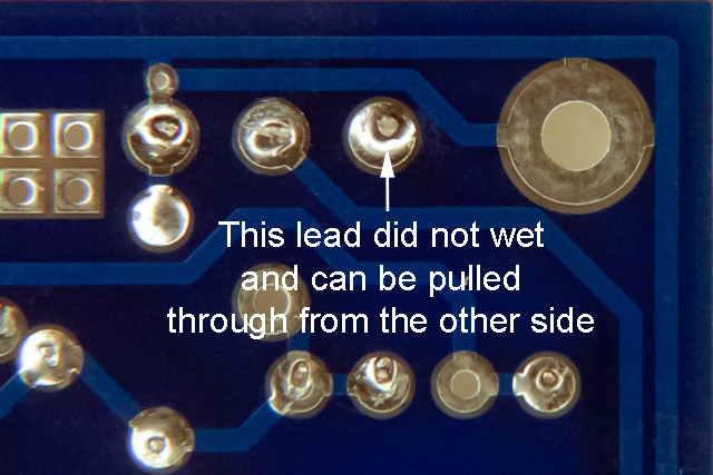
The number one problem I find in doing DIY module repairs is soldering issues: unsoldered pins, incomplete soldering, or solder bridges. You have to wash and carefully inspect every pad with magnification to find these. Here is an example of a resistor lead that did not properly wet and solder. This was a very intermittent connection that took some time to find. I was able to pull the resistor lead from the top side of the PCB out from the pad.
The next most frequent problems are missing parts, wrong parts and wiring errors. You have to use magnification and double check every component number and value. Wiring errors are frequently swapped signal and ground leads and swapped potentiometer leads. Use color coding when wiring as it makes it easier to see a ground, power, or signal wire. These errors requires no special equipment to find and fix - just time and attention.
After these come the more difficult errors of bad parts and insufficient design margin. You generally cannot find and fix these types of issues without test equipment and electronics knowledge. I have had to make some repairs where all the correct parts and values were used but the circuit failed to operate properly. Typically these required changing specific component values or modifying the circuitry to improve design margin.
For an older piece of gear the number one problem is intermittent connections due to tin connectors and sockets. Reseat every cable connection and all IC in sockets. Tin connectors will eventually fail - it is just a matter of when. Wiping the tin by removing and reinstalling cleans the surface of the tin. The next most frequent problem is bad electrolytic capacitors, typically in the power supply. After that the issues are just bad components or poor previous repairs. I find older 4000 series CMOS ICs more prone to failure. If the piece of gear is vintage, then carbon composition resistors, paper capacitors, and transformer windings are frequent failure items.
Proper Packing For Shipment
Modules need to be packaged well for shipment. They also need to be protected from static damage. DO NOT just wrap your bare module with bubble wrap as you risk ESD damage. Put it in a static bag or wrap it with aluminum foil prior to wrapping it with bubble wrap. DO NOT just pack the module loose in a box with styrofoam peanuts as they will all settle and your module will be smashed up against the package with small styrofoam remnants crammed everywhere!
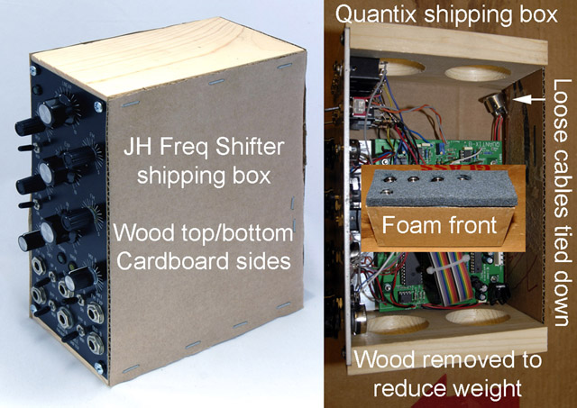
For some modules I have made a wood and cardboard inner shipping box to securely hold the panel and PCB. I simply cut a pine wood top and bottom with a small recess to fit flush along the panel edge and mount the module with wood screws and protective plastic washers. I staple on cardboard sides and a back (wood and cardboard retain moisture and will not generate static). I wire tie loose parts and cables through the cardboard to hold them securely. I sometimes will wire tie the rear PCB standoffs to the cardboard to keep the PCB bracket from flexing. I have cut out areas of the wood to reduce weight for international shipping. I sometimes add a foam cover to protect the knobs and switches prior to wrapping with bubble wrap. Here are photos of two modules that I recently shipped this way.
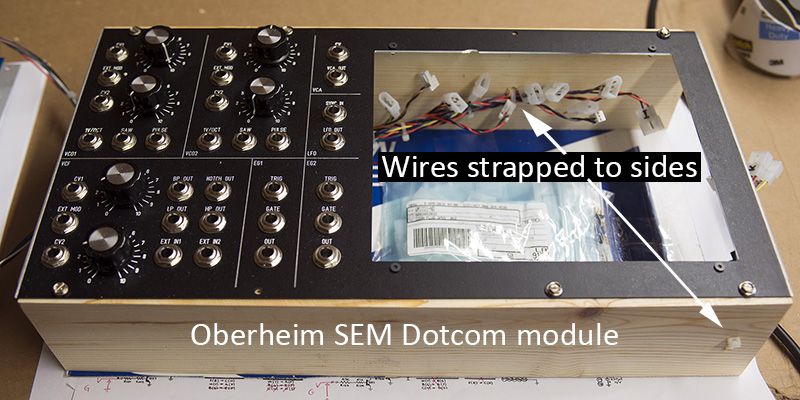
Here is a photo of a 8MU Dotcom Oberheim SEM. I needed wood reinforcement to keep the panel from flexing. I stapled a cardboard back to protect the wiring and the SEM PCB. I taped extra parts that I was returning to the inside of the cardboard.
Fakes (or just bad parts)
I sometimes get suspicious rare old parts when I am doing a DIY build repair or a DIY build for someone. Fakes are more prevalent nowadays, especially with eBay purchases. Sometimes I will create a test fixture to verify a part is indeed functional. Other times I will just verify it in the PCB.
I have seen several MN3005 BBDs that were a relabeled MN3008 which is half the length. In one case I reduced the clock rate so the total delay time was the same, albeit with lower audio quality.
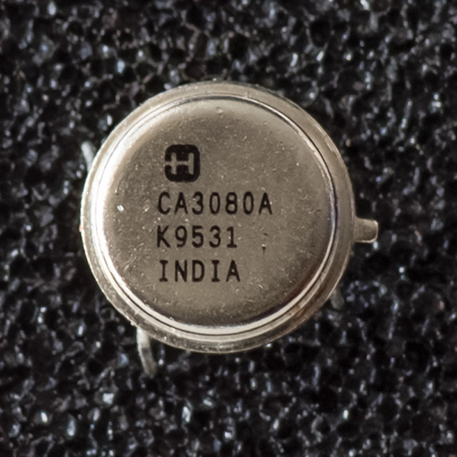
Recently I did a DIY build with a suspicious CA3080A in a can package. Can packages tend to be much earlier than this one dated 1995. I also don't remember Harris packaging in India. Either way, the part didn't work at all like an OTA and needed to be replaced.
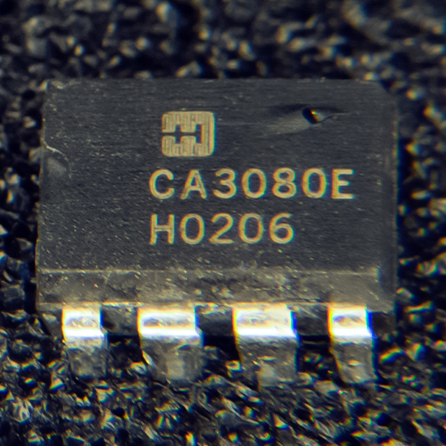
I recently got several of this vintage CA3080E in PDIP packages. Three of the four did not work. This defective one has a bubble on top as if it has been recoated and delaminated. I pricked the bubble with a pin to verify it was delamination. I have never seen an authentic part with this type of defect. I don't know when Harris phased out the CA3080E but this date code of 2002 seems a bit late. Usually there is more space between the H and the date code. Acetone did remove a black topcoat but the label underneath was the same. Another part with this same date code and marking is good.
One of the other defective parts got hot enough to melt the legs off the IC. Had I tested this in a PCB I might have damaged some small runs.
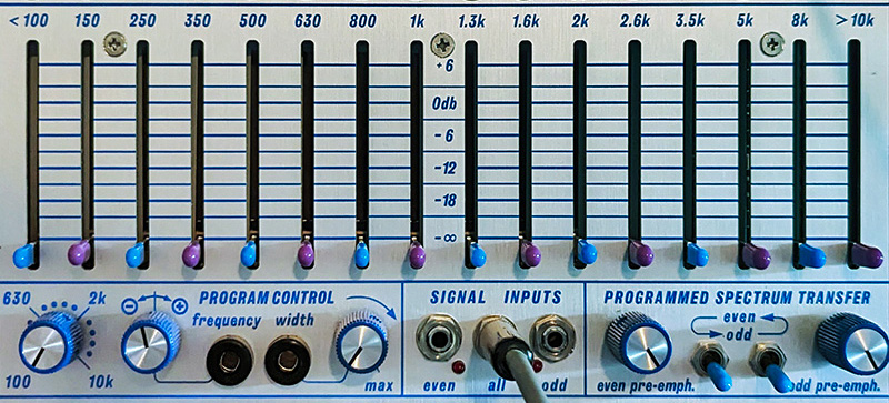
Violet Switch/Slider Caps
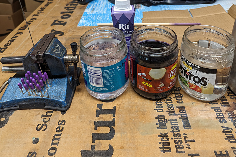
My 296 Programmable Spectral Processor has blue and violet banana jacks but violet switch caps are not available. I bought white switch/slider caps from Thonk and dyed them violet. I used purple Ritz Dye More. I made a holder for 16 slider caps from solid wire with the open end down. That way I could dye all 16 at once (two 296s) and have them match.
I filled three jars with boiling water and immersed the caps in the first jar to warm them and clean them of any oils. I mixed the dye in the middle jar until the color seemed dark enough. I then proceeded to dip them in the dye until I achieved the color I wanted, and then I rinsed them in the third jar. They were probably in the dye less than 5 seconds total. I carefully used my air compressor to blow away the excess water and dry them. Once dry, I used a can of compressed air so I could insert the nozzle inside to blow out any remaining moisture. This photo shows my setup after I was done.
This photo shows my holder and still-wet violet slider caps of uniform color.

This photo shows them installed on my 296.