|
Bridechamber |
|
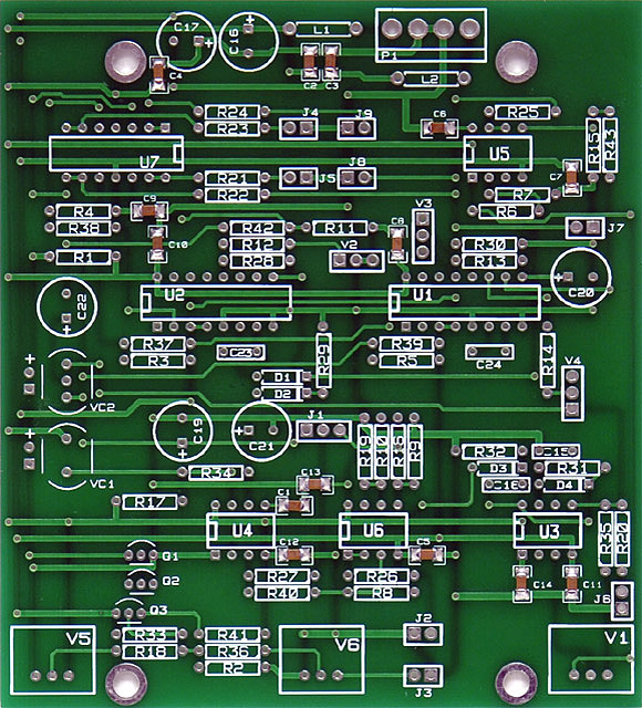
I purchased a Bridechamber Rev3 PCB for the Wogglebug as discussed on the Electro-Music forum. There are fourteen 1206 surface mount capacitors on the topside of the PCB.
|
Wogglebug schematic errors:
Required modifications:
|
Wogglebug schematics (with corrections #1, 2 and #4) updated
Wogglebug Mouser parts list updated
Modifications
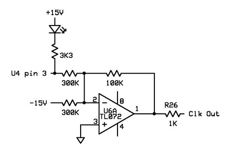
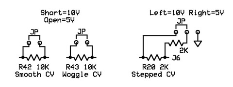
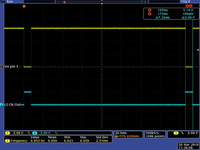
The LFO Out is a +/- 5 volt level fixed 7.4 mS negative pulse (top trace). I decided this output would be more useful as a 5 volt positive pulse to use as a variable clock and trigger generator (bottom trace). I also added a Rate LED and jumpers to select 5V or 10V CV outputs.
|
Additional modifications:
Assembly Notes:
|
|||||||||||||||||||||||||
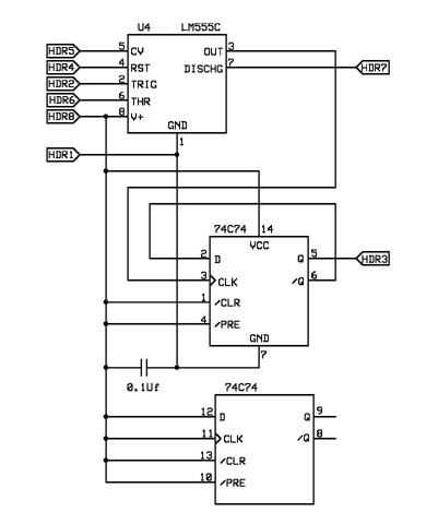
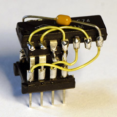
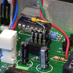
After the module was built, I decided I wanted the Clock Out to be a 50% duty cycle instead of the 7.4mS positive pulse. The rate was high enough that I could divide it by two to generate a square wave. Since U4 was in a socket, I used a header with a LM555C and a 74C74 which required no modifications to the PCB.
|
Clock 50% duty cycle modification:
|
Construction
The three traces cut for the clock modification are all hidden and I used R8 and R40 for two of the clock mod resistors. The third resistor is mounted on the rear of the PCB. This photo also shows the three jumpers I added to select the CV level.
| I made the two 2-pin jumpers by bending the leads to fit the PCB layout for R42 and R43. I then soldered 10K resistors between the legs and inserted the jumper into the PCB as shown in this photo. |  |
| The three pin jumper was a bit more challenging. Since only 1 pin soldered into the PCB the other pins slide in the plastic housing. I potted the two resistors and pins in epoxy to eliminate any movement and then soldered the jumper in the PCB as shown in this photo. The wire goes to a nearby ground via. | 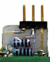 |
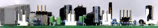
| Here is a side photo of the PCB showing the jumpers installed. | |
|
|
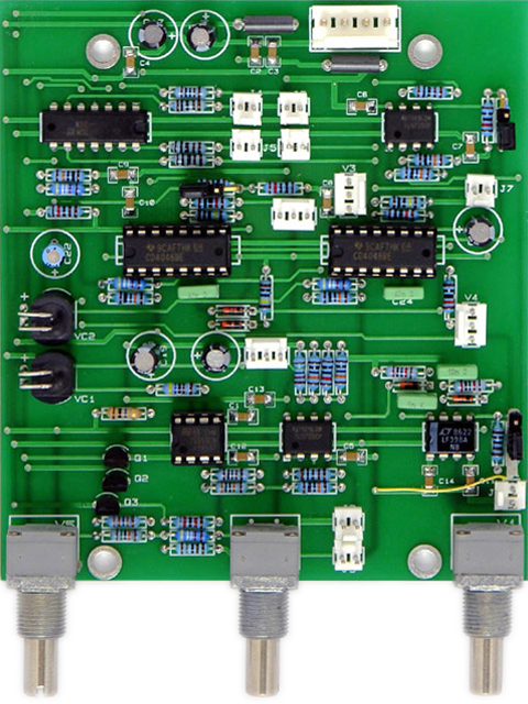
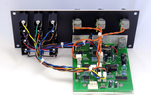
Wiring complete. The MTA insulation displacement connectors in the Mouser parts list have insufficient clearance for three of the closely spaced headers: J2, J5, J8. I substituted FCI mini-latch connectors which will work with the MTA headers although the pins are 0.065" too long.
Panel
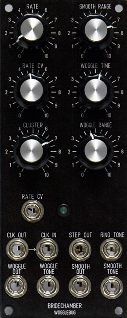
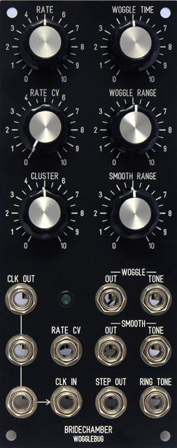
I built a temporary panel by using a spare MOTM-120 panel and printing a matching design on a laser printer. I glued it to the front of the panel and sprayed it with two coats of lacquer. The lacquer seals the page and gives it an orange-peel texture with just a bit of sheen (left).
After using this module for a while, I chose to design a FrontPanelExpress panel instead of using the Bridechamber panel because I wanted a Clock Out multiple (right). This provides a single external clock for use with my three ComputerVoltageSource and PSIM modules.
Wogglebug FrontPanelExpress file