 |
DJB-ComputerVoltageSource
"CVS" |
|
[Update Nov-2014 The AtomPro28 processor that this module is designed around has finally gone end of life. There is a larger AtomPro40 that is available and could be used.]
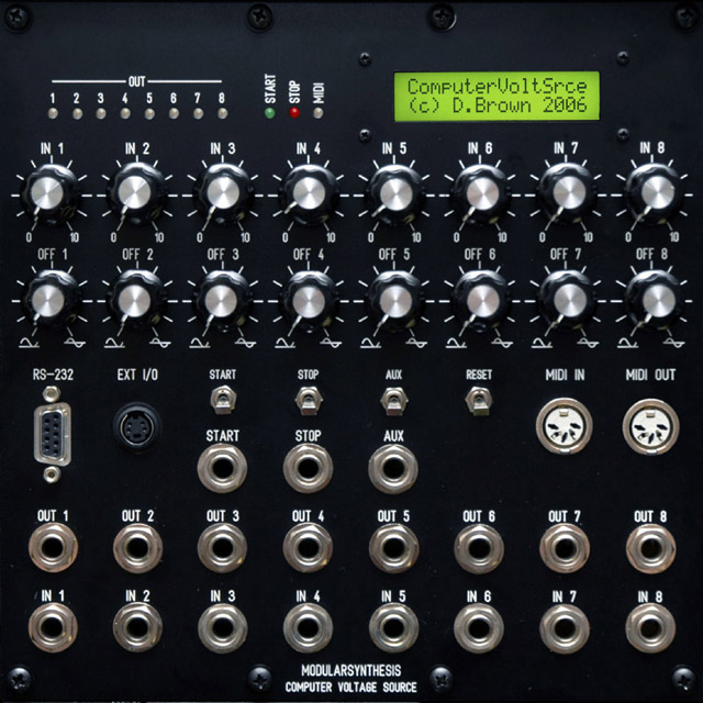
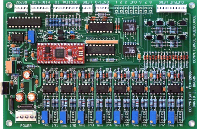
This page is a summary of my 8 channel voltage source module. The history of this module can be found on the Yahoo ComputerVoltageSources group. I co-developed the LCD_Support module, wrote the AVR assembly code, and designed a FrontPanelExpress panel. I also purchased an AtomPro28 to investigate and document the features since a data sheet was not available. The Yahoo group never reached consensus on a set of features and I wanted a full featured version so I decided to complete a PCB design for my own use. I started with the base schematics developed by Grant Richter with contributions from Harry Bissell, and modified them with additional features and functionality. My initial PCB design is definitely not a beginner's Synth-DIY project since it had no solder mask or silk screen, 0.012" ground plane pad clearance, small 0.056" component pads, SMT parts, and over 50 wires to the front panel.
This module features:
BasicMicro AtomPro28 processor
2 Kbytes data ram
31 Kbytes flash program memory
256 bytes non-volatile data memory
Eight 0 to 10 volt analog inputs (each input calibrated to
ADC value
1023)
Input attenuator controls normalled to 10
volts
Each input is summed with a 0 to 5 volt offset
control for +/- 5 volt input levels
Programmable reference voltages
Allow each bank of attenuator and
offset controls to be
read independently
so that all 16 controls can be used in
applications (e.g. my SuperSsequencer)
Eight 0 to 10.666 volt analog outputs and indicator LEDs
Start input, switch, and indicator LED
Stop input, switch, and indicator LED
Aux output or input and switch
Over / under voltage protection on all inputs and outputs
MIDI input, output, and indicator LED (interrupt 256 byte circular
buffers)
External I/O connector for additional input and output
expandability (100 Kbit I2C interface)
RS-232 computer programming port
Reset switch
PSIM software compatible (outputs 5-8 mirror outputs 1-4)
2 row x 16 character LCD
with eight programmable 5x7 characters
+15 volts at 130 to 190 mA, depending on the
brightness of the LEDs and LCD backlight
-15 volts at 28 mA
My favorite program is my CVS SuperSequencer. The 16 character display is nice for menu selection and the AtomPro28 non-volatile memory is great for saving sequencer setup. I used the Start and Stop switches and the Off8 control for menu options and selections. Various parameters are entered and stored. I've have a non-volatile memory map so I can allocate the 256 bytes across a number of different programs. This video shows the various parameters that are displayed on the LCD for the SuperSequencer program. There is also a video on my CVS Display page that demonstrates some of the setup operation using the LCD display.
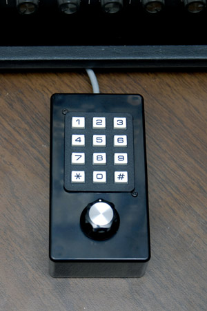
Using the Off8 control for user input was inconvenient so I build an external control module with a Velleman 12 key pad and an additional analog control. I use this external control module to set sequencer parameters and '*' and '#' function as the Start and Stop switches. The program will operate with or without the external control module.
AtomPro Processors
The AtomPro processor programs through an on-chip RS-232 port. Some USB to Serial adapters are not compatible with the AtomPro processors. I believe adapters that use the Prolific PL-2303 chipset are compatible.
The IOGEAR GUC232A USB to Serial adapter is compatible using Windows XP.
The Aluratek AUS100 USB to Serial adapter is not compatible with AtomPro processors.
Here is a photo of the original AtomPro28 using the Renesas H83664 microcontroller. The small 3 terminal IC in the lower right corner is an active Power On Reset circuit. The AtomPro28 Reset pin should not be directly grounded since this chip is actively driving the reset pin high. Ground the reset pin through at least a 47R resistor to limit the current (I use a 100R in the CVS). I have documented this and other details in my AtomPro FAQ.
Note: BasicMicro has since changed to the Renesas H83694 chip which has internal reset circuitry so they replaced the active Power On Reset circuit with a capacitor and diode. The key difference between these two Renesas microcontrollers is the hardware I2C circuitry which is not used in the AtomPro28.
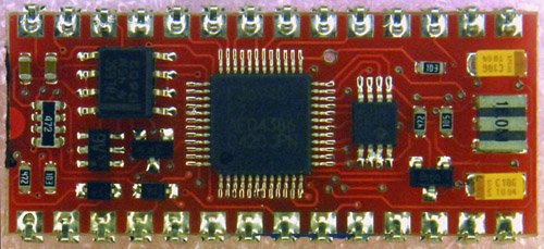
The AtomPro24 and AtomPro28 use resonators which are typically accurate to +/-0.5%. I modified an AtomPro28 by replacing the resonator with a crystal and two capacitors for accurate timing (the resonator is the block with stripes on the right side).
I wrote a program for my PSIM and my CVS that uses serial communication between the two modules to synchronize them. I sent the MIDI active sense byte ($fe) every 256 mS and used this to reset the real-time clock on the slave module. The video demonstrates the synchronization between two modules using this approach.
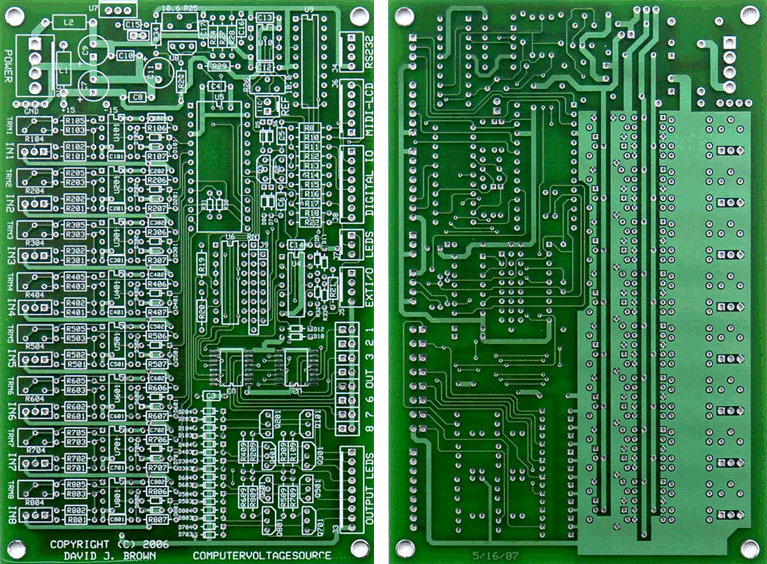
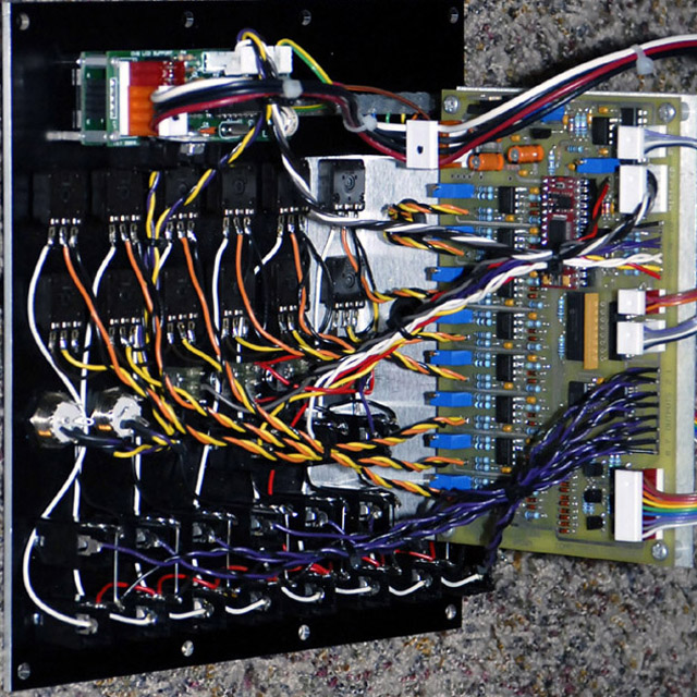
PCB and Assembly
This is the updated a rev2 PCB version. The board spacing is tight so I had to use 1/8 watt resistors in four places and utilize the MIDI circuitry on the LCD_Support PCB.
Here is a rear view showing the PCB mounting and panel wiring. The I2C busand power is brought to the Ext I/O connector for external expansion. I use this Ext I/O for my External Controls, my I2C to Serial bridge for a second MIDI output, and for my Analog/Digital Expansion for 16 additional analog inputs or 16 digital inputs/outputs.
Design Files
DJB-CVS design documentation includes specifications, schematics, parts list, FAQ, PCB layout and image. This design information, including the PCB layout file, is included in the Hardware CVS Module folder in the Yahoo ComputerVoltageSources group. The CVS FAQ is located in the database section in the same group and may contain additional entries.
DJB-CVS Main PCB design file is the design file for ordering boards from ExpressPCB. This board is economical when orderd in quantities of 8 or more. Check the ComputerVoltageSources group messages for information on a group buy of the PCB.
DJB-CVS FrontPanelExpress design file is a 5U x 5U MOTM-style panel using HPGL graphics to minimize cost.
CVS LCD design documentation includes software guide, schematics, parts list, FAQ, PCB layout and image (schematics, parts list, and PCB layout courtesy of John Loffink). This design information is included in the LCD_Support folder in the Yahoo ComputerVoltageSources group. The LCD_Support FAQ is located in the database section in the same group and may contain additional entries.
Additional Design Files
DJB-External Controls schematics for external 12 key keypad and analog control.
DJB-I2C to Serial bridge is a design to interface to the SpeakJet at 9600 baud. I have a 31250 baud version of this for a second MIDI output. Contact me if interested.
2X16 LCD Display and Design Files
The CVS uses a separate LCD_Support PCB for MIDI and the 2x16 display.
Build Configurations
DJB-Analog/Digital expansion is an extension my external controls design. This PCB supports an additional 16 analog and 16 digital inputs/outputs for either the CVS or PSIM.
I built a four channel module to replace my Synthmodules PSIM.
I built a minimal configuration CVS PCB as a dedicated ribbon controller for a Kurzweil PC2 ribbon.
DJB-CVS Programs
All of my operational and verification/calibration programs have been moved to my Programs page.
I have also documented a number of hardware and software details for the AtomPro24 and AtomPro28 in my AtomPro FAQ