|
DJB-019 |
|
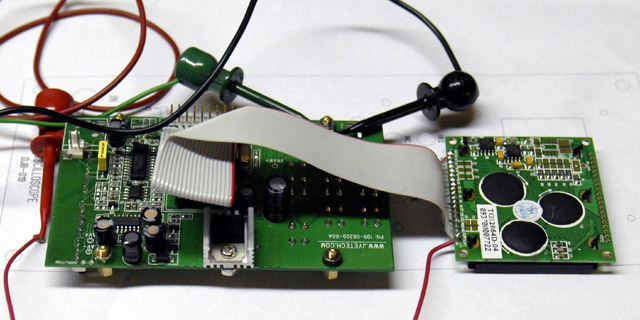
I built an LCD oscilloscope module using the JYE Tech 06201 digital storage oscilloscope purchased from NKC Electronics. I purchased the 06202KP kit with all SMT parts soldered but the LCD and all through hole parts unsoldered. I extended the LCD using a ribbon cable so I could move it above the PCB which I rotated 90º to fit in a 2U panel.
JYE Tech has since come out with an 06203 enhanced version that is available from NKC Electronics.
Construction
I did not implement the reference signal, external trigger, or the RS-232 interface on the module. I did install J5 on the PCB so I could access these features.
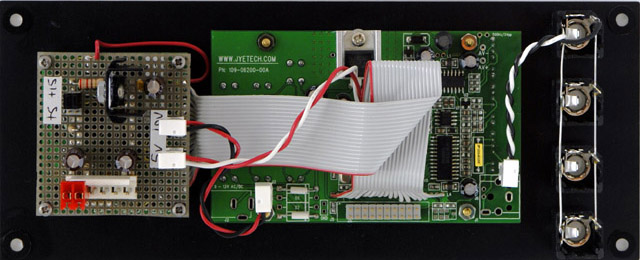
The LCD oscilloscope is designed for 9 to 12 volts AC. I eliminated the rectifier diodes and added a 0.1" MTA connector for 10 volt DC power. I designed an auxiliary PCB to mount on the rear of the LCD to regulate +15 volts to +10 volts. Using a 10 volt regulator splits the heat dissipation with the +5 volt regulator on the LCD oscilloscope.
DJB-019 Power supply schematics updated
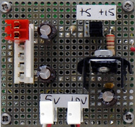
The LCD oscilloscope draws 110 mA from the +10 volts supply without the backlight. The backlight is normally wired to the +5 volt regulator and draws an additional 100 mA. I wired the backlight to the auxiliary PCB and added a series resistor to reduce the current but still provide reasonable brightness. Jumpers on the auxiliary PCB select either +15 volt only, or +5 and +15 volt operation.
|
LCD Oscilloscope current requirements |
||
| +15 volts | +5 volts | |
| Dual supplies | 48 mA | 105 mA |
| Single supply | 166 mA | |
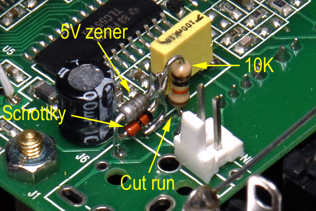
The frequency input is limited to 0 to 5 volts. I cut the frequency run on the PCB after the switch and added a 10K series resistor with a schottky diode to limit the negative voltage and a 5V zener diode to limit the positive voltage (I chose using a zener so I would only require connections to a ground pad). Alternatively you could limit the positive voltage with a schottky diode to +5 volts. If you don't want to cut a run, you can use R25 to limit the current and add the diodes after it.
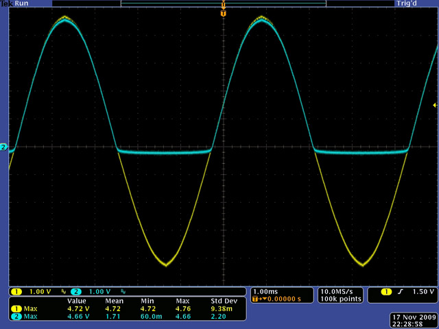
The input signal (yellow) is limited to -0.3 to +5 volts for the frequency circuitry.
Operation
The LCD is a nice display. The LCD oscilloscope has a 1V/Div that you can multiply by 1, 2, or 5. The 2V/Div fills the screen nicely with a 10V pk-pk signal.
The scope triggering works well if you have a repetitive waveform. The display does jump a bit if the waveform is non-repetitive but you can freeze (e.g. hold) the display to see the waveform. The oscilloscope has a larger sample buffer than the display so you can scroll horizontally through the waveform. The trigger point is at 25% of the acquisition buffer.
There are three operating modes:
SIG acquires on trigger then holds and displays a single waveform.
NOR acquires on trigger and displays (so will retain the last waveform if there is no trigger).
AUT acquires and displays continuously.
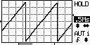
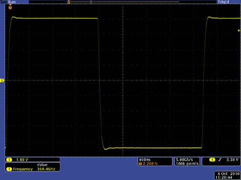
The new -200 firmware provides good resolution up to the maximum 0.5 µS horizontal scale. Below are the images of a 300 KHz square wave using a 1X probe daisy chained through to my 1GHz Tektronix scope.
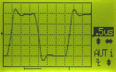
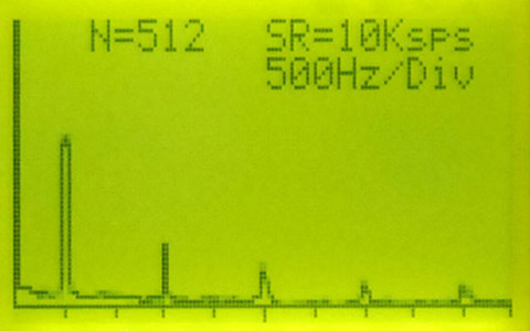
This image shows FFT mode of a 500 Hz square wave at 500 Hz/division. You can see the fundamental at the first division and the odd harmonics at diminishing amplitude at the 3rd, 5th, 7th, and 9th division.
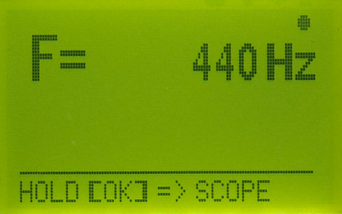
This image shows frequency mode and is very useful for tuning VCOs (remember the input voltage is limited to 0 to 5 volts).
Here is a short video of the oscilloscope with the -090 firmware (Note: the two issues mentioned in the video have been resolved. (1) -091 firmware corrects the difficulty in exiting from SIG mode when in HOLD. (2) It takes some time to return to normal mode after holding the OK button for 3 seconds and I tended to press it again which cycled it back into frequency mode.
There is a Google JYE Tech LCD oscilloscope group which is quite active and posts information on firmware updates.
There are also several videos on youtube that show the JYE Tech LCD oscilloscope
Video 1 displays a waveform and frequency measurement.
Video 2 displays various waveforms from a Noiz Box.
Firmware Updates and PC Interface
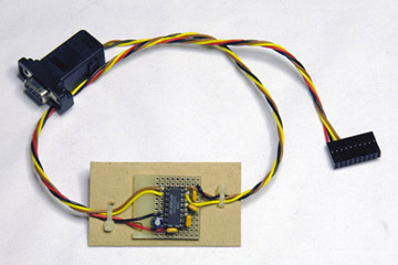
JYE Tech provides schematics for a TTL to RS-232 level interface but I chose to use a Max232 which required fewer parts. I verified the serial interface by uploading this screen capture from the LCD oscilloscope.
 |
|
DJB-019 Serial interface schematic
Using the boot loader to update the firmware is quite easy and JYE Tech provides good documentation on how to use the boot loader and the AVRubd program with a serial interface. There have been several firmware releases with significant improvements since my original -090 firmware version.
FW version -091: resolved the issue of changing from SIG mode when the scope is in HOLD.
FW version -092: added trigger output to cascade multiple scopes for multi-channel display.
FW version -100: added FFT functionality.
FW version -200: added equivalent-time sampling for high frequency display of periodic waveforms.
Panel
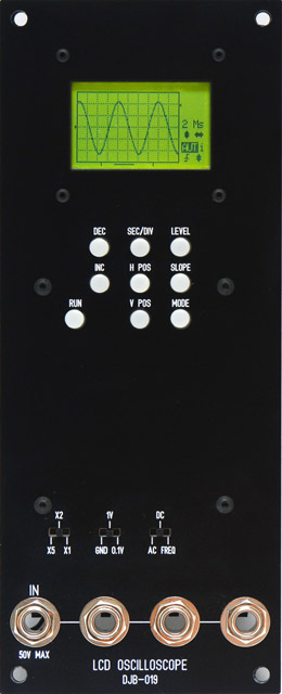
I used RUN, INC and DEC on my panel instead of OK, + and -. The on-screen menus refer to OK, + and - so I changed RUN to OK on the FrontPanelExpress design files.
I was surprised when my panel did not have the legends filled. I learned that there is an "in-fill engravings" box which must be checked on the panel properties. I updated the design files and used a white Artist's Oilbar paint stick to fill my engravings.
I have since changed the right jack to a BNC connector so I can use my 10X probes.
The front panel thickness is limited to about 2 mm due to the thickness of the push buttons. This is a standard 3 mm panel with an expensive 1 mm cavity milled in the back for the PCB to fit into.
DJB-019 LCD 3mm Oscilloscope FrontpanelExpress design file not built or verified
This is a 2 mm panel design which is much less expensive. I used 1 mm #8 plastic washers (Mouser 561-D832B) glued on the back at each of the four mounting holes to keep the module flush with adjacent panels. I moved the three slide switches up 0.25 mm from my panel as they were a bit low (I have verified this change only by a visual comparison of a print of the panel to the PCB).
DJB-019 LCD 2mm Oscilloscope FrontpanelExpress design file updated
Other Modifications
Here's some other modifications that could be made to the module using the 06201 LCD oscillocope: